holyandrei
Member
Hello, so I've search on this forum about this problem and also on internet and asked chatgpt. Did not found a possible root cause for this problem.
I have the following:
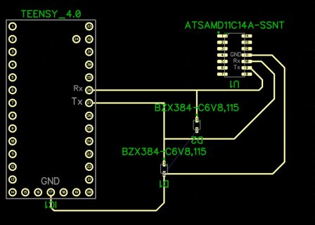
- Teensy40 using LPUART8(pins 20/tx and 21/rx) to communicate with atsamd11c14a on pins 9 (tx1) and 10 (rx1). There are 2 ESD diodes on each line to ground (BZX384-6V8).
The link is done as follows:
Pin Teensy/20/tx connects to SAMD11C14A/10/Rx1
Pin Teensy/21/rx connects to SAMD11C14A/9/Tx1
Why I ask for help:
- if I connect the atsamd11c14a to a usb-to-serial to the PC and send the command that I need, the atsamd11c14a responds with what I want.
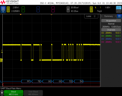
- if I connect teensy40 on the usb-to-serial to the PC and sniff the USB communication with Wireshark/USBPcap I can see the request command sent by teesny40 being the same with what I send when I test the previous point.
- when I connect both and try to send from teensy to atsamd11c14a then I get no reaction. atsamd11c14a is not providing the response I expect and observe when I test with the PC connection.
BaudRate config is 460800 on both.
Circuit is:

Could be that the problem is with atsamd11c14a. I will find a forum there and ask the same. Could be that the baudrate is not the same even if by the looks, they have the same number.
Code on teensy4 is quite simple:
#define PIN_LED 13
#define PIN_POWER_SET 6
void setup() {
/////////////////// PIN INIT ///////////////////
pinMode(PIN_POWER_SET, OUTPUT);
pinMode(PIN_LED, OUTPUT);
//as init enable power pin
digitalWrite(PIN_POWER_SET, HIGH);
digitalWrite(PIN_LED, HIGH);
delay(100);
//baudrate on teensy side, similar with the other MCU
Serial5.begin(460800, SERIAL_8N1);
}
#define PKT_LEN 6
uint16_t counter = 0;
void loop()
{
delay(1000);
//the request that I am also doing on PC and expect a specific response
//datatype is uint8_t since this is the input expected by "write" function in HardwareSerial library
uint8_t formatted[] = {0xFF, 0x7e, 0x00, 0x00, 0x53, 0x54};
Serial5.write(formatted, PKT_LEN);
//Serial is the USB teensy to log and trace the behavior
Serial.print("DataRead_");
Serial.print(counter);
Serial.print(": ");
delay(50);
while (Serial5.available() > 0) {
delay(10);
Serial.print(Serial5.read(), HEX);
Serial.print(" ");
}
Serial.println("");
counter++;
}
I have the following:
- Teensy40 using LPUART8(pins 20/tx and 21/rx) to communicate with atsamd11c14a on pins 9 (tx1) and 10 (rx1). There are 2 ESD diodes on each line to ground (BZX384-6V8).
The link is done as follows:
Pin Teensy/20/tx connects to SAMD11C14A/10/Rx1
Pin Teensy/21/rx connects to SAMD11C14A/9/Tx1
Why I ask for help:
- if I connect the atsamd11c14a to a usb-to-serial to the PC and send the command that I need, the atsamd11c14a responds with what I want.
- if I connect teensy40 on the usb-to-serial to the PC and sniff the USB communication with Wireshark/USBPcap I can see the request command sent by teesny40 being the same with what I send when I test the previous point.
- when I connect both and try to send from teensy to atsamd11c14a then I get no reaction. atsamd11c14a is not providing the response I expect and observe when I test with the PC connection.
BaudRate config is 460800 on both.
Circuit is:

Could be that the problem is with atsamd11c14a. I will find a forum there and ask the same. Could be that the baudrate is not the same even if by the looks, they have the same number.
Code on teensy4 is quite simple:
#define PIN_LED 13
#define PIN_POWER_SET 6
void setup() {
/////////////////// PIN INIT ///////////////////
pinMode(PIN_POWER_SET, OUTPUT);
pinMode(PIN_LED, OUTPUT);
//as init enable power pin
digitalWrite(PIN_POWER_SET, HIGH);
digitalWrite(PIN_LED, HIGH);
delay(100);
//baudrate on teensy side, similar with the other MCU
Serial5.begin(460800, SERIAL_8N1);
}
#define PKT_LEN 6
uint16_t counter = 0;
void loop()
{
delay(1000);
//the request that I am also doing on PC and expect a specific response
//datatype is uint8_t since this is the input expected by "write" function in HardwareSerial library
uint8_t formatted[] = {0xFF, 0x7e, 0x00, 0x00, 0x53, 0x54};
Serial5.write(formatted, PKT_LEN);
//Serial is the USB teensy to log and trace the behavior
Serial.print("DataRead_");
Serial.print(counter);
Serial.print(": ");
delay(50);
while (Serial5.available() > 0) {
delay(10);
Serial.print(Serial5.read(), HEX);
Serial.print(" ");
}
Serial.println("");
counter++;
}
Last edited:


