PaulStoffregen
Well-known member
I did some signal quality testing, to come up with a recommended source impedance. Luckily, a higher bandwidth scope is on temporary lone at the moment, so it's easy to see the transmission line effects. 
Here's how the signal looks after 12 inches of wire connected directly to the Teensy 3.0 pin, and a 12 inch ground wire located about 1-2 inches away from the signal wire. This is measured right at the WS2811 input, both the scope probe tip and ground.
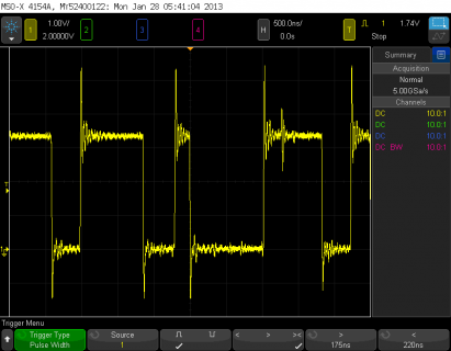
Here's the exact same wires, but with a 220 ohm resistor between the Teensy 3.0 pin and the wire going to the LEDs. Again, this measurement is the signal arriving very close to the WS2811 input.

If a tightly twisted pair of wires were used, a 100 ohm resistor might be more appropriate. But I believe this wiring setup is pretty typical of how many people will probably connect their LED projects.
Here's how the signal looks after 12 inches of wire connected directly to the Teensy 3.0 pin, and a 12 inch ground wire located about 1-2 inches away from the signal wire. This is measured right at the WS2811 input, both the scope probe tip and ground.

Here's the exact same wires, but with a 220 ohm resistor between the Teensy 3.0 pin and the wire going to the LEDs. Again, this measurement is the signal arriving very close to the WS2811 input.

If a tightly twisted pair of wires were used, a 100 ohm resistor might be more appropriate. But I believe this wiring setup is pretty typical of how many people will probably connect their LED projects.


