teensy4.1 / dac8568 cs line crosstalk

i had been prototyping a small board with a few dac8568 and my teensy 4.1 and all was well but when i had a custom pcb produced i noticed individual cs lines on all dac's toggle despite it not being communicated too, im putting it down to inteference on a pcb level but just wanted to see if any users experience cross talk on cs lines before...
 
in my code i write the digital high and pull low for transmit, it worked really well in prototype, do you think pull up res will help? if so 10k? 100k? thnaks
 
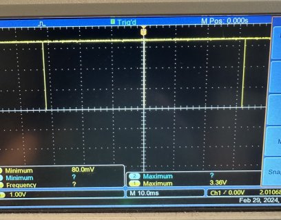
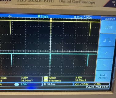
Can you give us more detail? You said "noticed individual cs lines on all dac's toggle". Can you describe how you noticed? Did you use an oscilloscope to observe the signals? If so, can you show us the screen? Or if you're not directly observing the signals but rather inferring they must all be toggling, can you describe the actual things you observed with your eye or other senses? Signal quality issues are tricky and even very small details can really matter.

With pretty much any strange problem, I would first check the software side before diving into signal quality. But you said it ran fine on the prototype. Are both supposed to be the same design, same number of chips, same pins on Teensy? If they differ, best to really investigate if a "simple" mistake was made before looking at the tough analog nature of signal cross talk.

If it really is signal cross talk, usually 2 things can be done.

#1 - Improve ground routing. Best is a 4+ layer PCB where an unbroken ground plane is directly underneath the signals. What matters is the total size of the 2D area formed by the loop of the signal and its return ground path. With a ground plane the area is very small because it is so thin, only the thickness of the internal PCB layer. On a 2 layer PCB, the loop area will be much worse. You might need to add many redundant ground paths, and make room to route ground alongside all sensitive high speed signals.

#2 - Add a series resistor, ideally close to Teensy (or whatever is transmitting the signal). Start with 100 ohms. The resistor has 2 benefits. First it helps to match the transmitter to the characteristic impedance of the wire+ground, which lessens problems like signals reflections. Second, it tends to act has a low-pass filter together with the tiny capacitance of the input pins (usually about 5pF each) and PCB trace (usually very small, especially on 2 layer boards where these problems are worse). Cross talk tends to be a very high frequency problem, so just slowing the rising and falling edges ever so slightly can really make a big improvement.
 
im using an oscillosope on a 6 layer board with an internal gnd plane on layer 2 and 5.
the toggles look quick and appear on all cs lines, ive attached a photo.
everything is the same software and pinwise from proto to pcb - ill try some pull up res now
 

Attachments

  • cs line toggle.jpg
    cs line toggle.jpg
    252.9 KB · Views: 10
Just wondering, this looks a bit too ideal (full 3.3V scale, pulse shape) to be a crosstalk. Have you checked the CS lines with a continuity tester if there is a short between them and/or a different signal?
If everything worked as a prototype but not on the PCB (a 6 layer one with ground planes), the logical conclusion would be to double check the PCB design, test for shorts etc.
 
so strange, i tried a pull up res on all cs lines and that did not help i then cut one cs line trace completely and bodge wired directly with 100 ohm res in series and still not working!
 
Difficult to understand that scope picture, as it doesn't show the time scale. It's also only 1 waveform. Normally for diagnosing cross talk problems, you would connect 2 channels... one of the aggressor signal and one to the victim signal (or if more than 2 channel scope, to multiple victim signals to see whether they are affected similarly or differently, but you can do this same with 2 channel and patience by just repeating the measurement for each victim signal). And normally you would capture on a "zoom in" time scale to see the shape of the rising or falling edges.
 
Please turn the horizontal knob to a shorter time scale. At this slow time scale, we can see the waveforms repeat every ~32ms, but we can't see the detail within that short pulse. Cross talk is a high frequency effect. You can't possibly hope to diagnose it with this slow time scale.

all cs lines share the exact some waveform in time, it must be pcb design

If they look the same shape, then yes it's much more likely to a PCB design or build problem. Crosstalk will usually show rectangle shape on the aggressor (because it is a digital signal driven both high and low by transitors) and sharp spikes with quick roll off on the victim signals (because they're driven only by high frequency coupling through the capacitance between signals and then return they gradually back to normal after the rapid coupling event).

With power off, you might try an ohms measurement between the signals. If they're shorted together or connected by a part like a resistor, the ohms measurement should show it.
 
Last edited:
Back
Top