Connecting the Teensy 4.1 USB data lines to a host PCB

Davidelvig

Well-known member
I'm transitioning from a Teensy-3.2-based design to 4.1, and was planning to use the off-the-shelf Teensy 4.1 on a custom PCB.
I want to use USB C on the outside (through the enclosure).

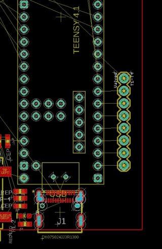
I have the board layout segment as attached, but just realized that the micro USB data pins are only exposed through the USB plug, or perhaps, using a pogo-pin connection on the bottom.

Any guidance on how to reliably connect the USB micro data pins on the Teensy 4.1 with a USB C connection (J1) on a host board?

Thanks! Teensy41_DirectMount.jpg
 
Yes, the Data +/- are just small pads - it should work with POGO pins - or PCB castellated cuts could pick those pads up perhaps. Best routing to the USB-C socket would be needed as the USB is 480 Mbps.

PJRC's beta baseplate boards for T_4.0 had USB Host and SD socket pins - and other larger pads all picked off with POGO and they worked - as long as the socketed T_4.0 didn't get pushed up from all those springs.

There was another USB-C adapter mentioned recently - perhaps for the T_4.1? That was just a small end mount adapter IIRC.

<edit> for T_4.0 - before release of T_4.1 @FRDM made a castelated board that placed solder on all underside pads and that worked as did the @loglow/talldog board that used a ribbon cable to pick up the SD and USB Host pins.
 
Last edited:
After a bit more thinking and option swapping, I'm thinking the pogo-pin option for the USB data lines might be best.
@Paul S, I know you use a "bed of nails" for testing.

I'm considering 2 pogo pins for just the D+ D- lines under the Teensy 4.0 or 4.1.
The board itself will be soldered via most/all of it's side pins, spaced above the main board with a row of plastic (.1") spacer material.

Any specific part recommendations for a pogo pin that could address this?
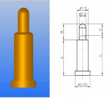
Perhaps this one?

Will pogo pins in this use have sufficient contact to serve as D+ and D- contacts for USB?
 
These T_4.0 beta breakout noted in p#2 were all POGO: pjrc.com/breakout-board-for-teensy-4-0/

Included usable USB Host in that case. That blog post shows the pins used.

Yes, the Test T_4's jigs are POGO based - pictures posted somewhere not found. Multiple layers of drilled plastic in that case to support many long pins locating to the right spot for all underside connections to test.
 
I'm headed for pogo pins.
At JLCPCB.com I find this part as one of their highest stocked parts.
I'm planning to mount the Teensy 4.1 on male header pins with a typical 2.4mm tall plastic spacer (the one that comes on the header pins).
This is my first venture using pogo pins.
In the linked data sheet, I think I want 2010 variety (3rd row in the data sheet), right?

PogoPic.jpgPogoTable.jpg

Thanks!
 
p# 8 links has this note:
Connections to Teensy 4.0 Bottom Side
To connect to the bottom side of Teensy 4.0, the breakout board uses these spring-loaded pogo pins. Either 12 to 12.5 mm height can be used for the pins which touch the flat surface mount pads. 12.5 works best to contact to the On/Off and VBAT pins.

That board had 'normal' male headers on the PCB.
 
The breakout board used for the Teensy 4 beta test (back in 2019) used a 12.5mm through-hole pogo pin. Scroll down to "Connections to Teensy 4.0 Bottom Side" for photos and a link to RTLECS. If you buy from Aliexpress, be careful to select the correct "color" for 12.5mm height, if your Teensy has normal headers and standard height sockets.

As others have mentioned, the test pads on the bottom of Teensy 4.0 are only for USB host (and you will see the breakout board used them to gain a normal USB-A host connector for easy testing of the USB host port). You can't get access to the USB device signals on Teensy 4.0 using pogo pins.

You can access the USB device signals with pogo pins on Teensy 4.1.
 
Great!
I'll get the 12.5mm for the test boards, and probably plan to use the shorter ones (3.0-3.5mm) in production when I need to fit in a slimmer enclosure.
I really appreciate the help!
 
Great!
I'll get the 12.5mm for the test boards, and probably plan to use the shorter ones (3.0-3.5mm) in production when I need to fit in a slimmer enclosure.
I really appreciate the help!

Did you end up going into production with your design? What length pogo pins did you end up using?
 
Yes, though with some caveats.

I have three short pogo pins right under D+, D-, and the same pin under the Teensy's VUSB. I use these from LCSC through JLCPCB (if that alphabet soup makes sense.)

JLCPCB complains about the holes in my board under the pogo pins (which require none), but I'm staying flexible for different pins.

I really should use a regular single header pin on the VUSB, and I'll use that some time soon. At present, I solder down through the VUSB hole on the Teensy to assure I have good VUSB connection to that pogo pin.

For the next 25 units at least, this is my production process.

I still wish for better.

  • A native USB C Teensy would be a dream
  • pin holes for D+/D- would be a help
  • Using a short USB Micro to USB C cable is still a possibility, and creates some opportunities to rearrange to board inside the enclosure at the cost of a cable and other parts.
So... production-ish.
 
Back
Top