I thought I had a way to overwrite the screen with constantly updated data, but isn't working that well. I have the output of a digital read out head (DRO) being output to my ILI9341. Just got it connected up. Some parts of the rectangle have remnants of previous readings. The way I did it, has worked for other sections of my code, so I am puzzled. However, I'm not sure if what I am doing is the "right way" or even close to the recommended way. Here's a copy of the function I use to update the X DRO.
I am using the ILI934_t3n library. thisGREY is just some background color. cxgX and cygX are the coordinates on the screen for the number to be displayed and are uint16_t. Xval is updated by @luni's EncoderTool. I use this basic code to update my RPM of my lathe, and I have not noticed the artifacts, like I see with this code.
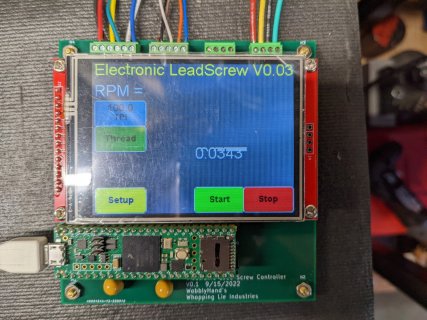
Probably doing it wrong - I'm not a very good C or C++ coder. Is there a better way of doing something like this? Here's a picture of the sort of artifacts that I am seeing.
I have seen it on both the X and Z DRO displays, but not the RPM. You are seeing my first PCB made with KiCAD. It is for an Electronic Lead Screw for my lathe. It cuts threads in metric and imperial and feeds in both units. That part is working well. So far I have not had to make any changes to the PCB. I am now adding in the DRO inputs. The X DRO wires are coming in at the top right connector. The DRO display is not calibrated - I will have to determine the calibration coefficient at a later time. But it would be helpful to be able to read that displayed number.
Thanks for any insights.
Code:
void updateX()
{
  if (Xval != oldXval)
  {
    uint16_t x1, y1, w, h;
    oldXval = Xval;
    String newstr = "XXXXXXXX";
    tft.setFont(Arial_18);
    tft.setTextColor(ILI9341_WHITE);
    tft.getTextBounds(newstr, cxgX, cygX, &x1, &y1, &w, &h);
    tft.fillRect(x1, y1, w, h, thisGREY);
    tft.setTextDatum(BL_DATUM);
    tft.drawFloat( Xval, 4, cxgX, cygX );
    Serial.printf("Xval = %+7f4\n", Xval);
  }
}Probably doing it wrong - I'm not a very good C or C++ coder. Is there a better way of doing something like this? Here's a picture of the sort of artifacts that I am seeing.
I have seen it on both the X and Z DRO displays, but not the RPM. You are seeing my first PCB made with KiCAD. It is for an Electronic Lead Screw for my lathe. It cuts threads in metric and imperial and feeds in both units. That part is working well. So far I have not had to make any changes to the PCB. I am now adding in the DRO inputs. The X DRO wires are coming in at the top right connector. The DRO display is not calibrated - I will have to determine the calibration coefficient at a later time. But it would be helpful to be able to read that displayed number.
Thanks for any insights.