Is there a simple way to log output serial data?

clinker8

Well-known member
I have an electronic lead screw (ELS) project that I completed a couple of years ago. It's probably 3000+LOC. I'm using a Teensy4.1 and it's been working flawlessly. I'd like to augment the capabilities, and I'm finding it tough to log the data that I need, to prove to myself that the ELS is working as I expect. I'm adding an exponential deceleration to my stepper so that the carriage stops with little to no overshoot. I need to test that it is working with the right profile.

The Arduino IDE output window is grossly deficient, I need to save many thousands of points, but it will not allow copying that many lines. It would be useful to log the data on the usbserial port, which is already connected to my Mac.

I tried
Code:
% screen -port /dev/cu.usbmodem119047801 115200
I was able to capture some data, but unfortunately not all of it. Might be my terminal settings, I will check. It seemed I captured only a small fraction of the data. Roughly I want to capture 20,000 points, basically 20mm of travel sampled every micron. I'm getting about 50 lines of data.

What is the correct baud rate for the connection?

All that I'm trying to log is the spindle velocity, number of cycles, and the position of the carriage, or in code terms:
C-like:
Serial.printf("%f, %i, %f\n", RPM, ARM_DWT_CYCCNT, ztogo);

In screen, I'm not getting carriage returns, only line feeds. But it is being interpreted correctly in the IDE window. Might need a \r?
Edit: Using \r messes up both the IDE and the screen output.

However, using the screen app, captures the usbmodem. I found a way to release it, but it's not something I want to do long term. Is there a way to promiscuously monitor the port?

Is there something less painful to do? Been beating my head against a wall, and thought I'd ask if there was something more productive to try!
 
I'm using Arduino 1.8.19 and TD 1.59 on Windows 10, and I've always been amazed at the speed of the serial monitor.

I wrote the short program below to write to Serial every 1 us, and I get all of the expected data, which is 20000 lines, each starting with a count value that goes from 1 to 20000. I get all of the lines up to 175,000, and then it must reach some buffer limit, and I just get the last ~175,000 lines.

There are memory limits, so you can't just log to the serial monitor at a very high rate for a long time and expect it to hold however much data that turns out to be. Can you put in a trigger so that logging starts and stops automatically and you get the data you want?

You say you are getting 20000 lines for 20 mm, or 1 line per micron. Is the logging rate actually based on the rate of the lead screw, or is it a fixed frequency. If it's a frequency, what is it? Do you have a fixed control cycle?

You could also log to SD, but you have to be careful to do so in a way that does not disrupt your control cycle.

Code:
uint32_t current, prev, count;

void setup() {
  Serial.begin( 9600 );
  while (!Serial) {}
  prev = ARM_DWT_CYCCNT;
}

void loop() {
  current = ARM_DWT_CYCCNT;
  // write every 1 us (600 cycles @ 600 MHz)
  if (current - prev >= 600 && count < 175'000) {
    prev += 600;
    count++;
    Serial.printf( "%10lu %10lu %10lu\n", count, current, current );
  }
}
 
Thank you for the example. And thanks for the formatting code, forgot the long unsigned format!

The logging event lasts for maybe ten seconds, while the carriage moves to a stop. The output rate is controlled by the feed rate, which is programmable.

Lets see, at 400 RPM what kind of rate do I have at 0.25mm/rev
400 rev/min * (1 min/60 sec) * 0.25mm/rev * (8mm/2.1166mm) *1000 um/mm * 1 pulse/1um = 6299.411 pulse/sec for 5 seconds, then exponentially slowing down to 0 pps for the next 5 seconds. (The 8/2.1166 factor is because my test lead screw is 8mm lead, but the actual lathe lead screw is 2.1166 mm lead (12 TPI).)

The desired sigmoidal velocity function is of the form y = [ L/ (1 + exp(-k*(t-t0)) ) ] + b. This is synthesized because the exponential factor I am calculating on the fly on the displacement is an exponential. At least my simulations show this. So I need to test, in that my lead screw is slowing down in velocity with a sigmoidal (s-curve) form. Hence the need for some logging.

The print statement is only called when the carriage is in motion. As the exponential gets larger and larger, the print statement is called fewer and fewer times (since the exponential factor is slowing the velocity). I have found, to my chagrin, that I haven't yet calculated my lead screw velocity, which is what I want to know. I had plotted the spindle RPM, which remains constant, oops! Need to calculate the lead screw step rate (velocity) in the right place. I found experimentally that the values of the exponential were changing at fairly high rates, compared to the velocity. That makes sense, as the sigmoid function has regions of flatness, then regions of slow transition, finally a linear slope region, and then slow exponential ramp down to zero.

I was using IDE2, which seems to have different capabilities. You can see the data scroll by, but you cannot capture the entire event. Indeed, there's no select all for that window. I can find no documentation on changing the IDE2 Serial Output buffer size, it seems to be hardwired - which in my humble opinion is a very bad idea. Manually selecting all, only results in the last 50 or so lines of output, which isn't useful. Likewise, the plotting function only allows a measly 500 points to be plotted, not terribly useful (at least to me).
 
Well, I'm trying to :)
The rate starts out kind of fast, and I'm trying to measure the velocity, by measuring stepper pulses in a time window. Problem is that the stepper pulses are quantized, and I'm not getting enough of them to get a decent velocity measurement. So I'm alpha filtering, but still running into problems. Plus the usual scope of variable issues. Good grief, this is kicking me to the curb...
 
Well, what is the time window over which you are counting stepper pulses, and how many pulses per rev (PPR)? If you need more frequent speed measurements, or higher-resolution speed measurements, the alternative to counting pulses is to measure the period of one or more pulses. The T4.x library FreqMeasureMulti is very good at that.
 
Well, what is the time window over which you are counting stepper pulses, and how many pulses per rev (PPR)? If you need more frequent speed measurements, or higher-resolution speed measurements, the alternative to counting pulses is to measure the period of one or more pulses. The T4.x library FreqMeasureMulti is very good at that.
I must be having a mental block. Much of the morning has been unproductive - SW wise. One of those days I suppose.

To answer your questions:
1. 50ms
2. should be 800 microsteps to make a revolution. 4 microsteps/step x 200 steps/rev

Issue is having to measure over a longer interval than 50ms. Sometimes there are no pulses within the 50 ms interval, especially when slowing down. Measuring the individual periods of the pulse train would be useful.

It's unclear to me, if FreqMeasure or it's variants are blocking, or how long they take (or what timer resources they use). I am using pin 5 for issuing pulses. Also using two instances in my code with PIT, for one shot timers. (Can't blow them up!).

I will check to see if I can get FreqMeasure working harmoniously with my code.

Where can I find the source code for FreqMeasure? Here's a link at least for how to use: https://www.pjrc.com/teensy/td_libs_FreqMeasure.html. There it states that only pin 22 can be used to measure frequency. That's not possible for me, I am using that pin for a linear quadrature encoder. Is there more current information on FreqMeasure? Of course, I'm trying to measure as close to zero as possible... Just where things get messy :)
 
FreqMeasureMulti is similar to FreqMeasure, but can be used on a large variety of pins. Both libraries are included in TeensyDuino, so you should already have them on your system. Neither is blocking. They use the input capture capability of various hardware timers. Each rising edge on the input pin triggers capture of a running timer and generates an interrupt. The ISR reads the capture value and writes it to a FIFO, so it uses very little CPU. Your code just has to poll the FIFO via the available() function and process data as it arrives, so there is no blocking.

I don't understand what you mean by "issuing pulses" on pin 5. Do you mean counting pulses?
 
I don't understand what you mean by "issuing pulses" on pin 5. Do you mean counting pulses?
Pin 5 is an output in my system. I call it PUL, because it is connected to the stepper motor driver pin of the same name. When PUL goes high, my stepper motor advances (or goes the opposite direction depending on the level of the DIR pin) one micro step.

Thanks for the explanation of FreqMeasureMulti, it is appreciated.

As an aside, it would be good (in the example files) to explicitly state that in FreqMeasure you had to connect to pin 22. That was not obvious in the comments!

FreqMeasureMulti was ok comment wise, as it seemed pin numbers were used. But there wasn't an explanation that they were indeed "input" pins. When I quickly looked at FMM, I wasn't sure what the "numbers" were, pin numbers, or some magic sauce. The header file didn't give me any additional insight. I'll see if I can cobble FMM into my code. Once I know stuff (is roughly) working, the code will be ifdef'd out.
 
Since PUL = 5, and it is an output in my system, how can I monitor the pin? Once I incorporated the FreqMeasureMulti, and said to use 5 as an input, did it overwrite it? Do I need to physically wire the output pin to a separate pin? Due to enormous code length I can't show it.

C-like:
void pulseme()   // turns off stepper pulse after time out.  TeensyTimerTool OneShotTimer callback
{
  digitalWriteFast(PUL, LOW);         // ends the stepper pulse
}

void setup()
{
    stuff...
    freq1.begin(PUL);   // measure the frequency of PUL. New stuff
}

void loop()
{
  if (timeout)  // if no timeout, skip this
  {
    timeout = false;     
    // determine how many counts we get in 20ms, base for a speed estimate
    t2.trigger(20ms);     // set RPM timer to go off in 20ms
    valstart = val1;      // save current position
    displaycount += 1;
  }
  if ((myrpm == 0.0)&&(first) && encoderactive )
  {
    Serial.printf("%7.1f%\tRPM\n", myrpm);  // there's a zero bug of some sort
    displayRPM(-myrpm);
    //Serial.printf("%i = counter\n", SpindleEnc.getValue() );
    first = false;
  }
  // note: need a way to display 0 rpm when the lathe stops!  not doing that.
  if ( (myrpm == 0.0) && (displaycount % 500==0) && encoderactive && (menu==0)) {
    displayRPM(-myrpm);   // ok to display once every 1 seconds.  At least it goes to zero!
    // Only display RPM in menu 0
  } 
  if( (myrpm == 0.0) && (!encoderactive) ) {
    if ( (displaycount % 500 == 0)  && (menu==0 ) )
      displayRPM(-myrpm);
    displaycount += 1; 
    // In beginning encoderactive = 0, and displaycount never increments.  Add this to prevent initial flicker
    // 500 chosen with delay(2) to give a rough 1 sec update
  }
  if ((myrpm !=0) && encoderactive)
  {
    first = false;
    if ( displaycount % 50 == 0 )   
    { // slow down the display calls to 2.5 Hz!  20 x 20ms = 400ms = 2.5 Hz
      //Serial.printf("%7.1f%\tRPM\n", myrpm);
      displayRPM(myrpm);
      //Serial.printf("count value = %i\n", SpindleEnc.getValue() );
    }
  }
 
  updateDROs();     // Get positions of linear encoders
  readconsole();    // look for incoming debug commands via serial
  processTouch();   // process the touch screen and set up states

  doStateMachine();  // this section runs the state machine... button presses cause us to change states
  
  // new stuff
  if (freq1.available()) {
    sum1 = sum1 + freq1.read();
    count1 += 1;
  }
  if (pulsetimeout > 100) {
    if (count1 > 0) {
      Serial.println(freq1.countToFrequency(sum1 / count1));
    }
    sum1 = 0; count1 = 0; pulsetimeout = 0;
  }
  delay(2);
}
I'm getting zero pulses out now... It seems I need two pins.
 
A good reference for what the USB Device to Host Serial rate can be is this sketch. It starts fast and then at some point UI will get behind the buffers as long as they can even keep up. https://github.com/PaulStoffregen/USB-Serial-Print-Speed-Test

There is this doc making the pins clear as they change between Teensy devices: https://www.pjrc.com/teensy/td_libs_FreqMeasure.html

Given the concern is the end phase of the movement - could the early full speed output be minimized to prevent USB overload before that 'slow down' portion? Perhaps the ~10 seconds of data could all be saved in RAM1 or RAM2 or on PSRAM and then sent out upon completion for review?
Thanks. I have a T4.1. I got the stepper to work, but apparently not the FreqMeasMulti yet. I physically wired Teensy logical 5 (pin 7) to logical 34 (RX8) and did pinMode(34, INPUT) in setup. Even though the stepper moved 8mm, (and there were over 1600 stepper pulses,) FreqMeasureMulti failed to output anything. The pulses were roughly constant frequency, as I just did a feed command for 8mm. I'll have to check my wiring with a scope. The signal is on pin 34. Does FreqMeasureMulti assume a minimum pulse width? I am using 2 microseconds pulse width for my stepper.

Alright, have a clue. At this slow feed rate, the period is 8ms. So not a high frequency. So I can't average too much, or it will take a long time, longer than I have. I need a wider measurement window than 100 ms. I'll try 500ms, it's better than nothing.
 
Okay, pin 5 is your stepper output. FreqMeasureMulti measures the period of an input signal. Do you have a speed / encoder input?
Not in the classic sense. I have a rotary encoder for my spindle, but not for my stepper.

I was using the stepper pulses as the input. Now wired to logical 34 aka Rx8.

At the moment, the period of the pulses is 8ms (125Hz) with a pulsewidth of 2us.
 
It seems freq1.available() never is 1. I never increment count1. Seems strange to me. Yeah, I chose an illegal pin. There should be error checking on this... This was a silent fail...

From: https://github.com/PaulStoffregen/FreqMeasureMulti

Allowed pins. 34 is not allowed. I will try 33.

Teensy 4.1 0-9,22-25,28,29,33,36,37,42-47, 48-50(dups),51, 52-53 (dups), 54
 
Ok, for the purposes I'm interested in, I think I have a solution. Changed to pin 33. This is what I measured. I have no idea what the time stamps are yet, but this isn't too bad. Kind of showing me that the basics are working.

Code:
Special fcn stepper enabled
Vel of stepper = 0.668157, Distance to stop = 20.615999
Vel of stepper = 251.199905, Distance to stop = 19.868000
Vel of stepper = 251.083008, Distance to stop = 18.774000
Vel of stepper = 251.088882, Distance to stop = 17.559999
Vel of stepper = 251.250397, Distance to stop = 16.339001
Vel of stepper = 251.061996, Distance to stop = 15.086000
Vel of stepper = 251.128830, Distance to stop = 13.846000
Vel of stepper = 251.162888, Distance to stop = 12.599999
Vel of stepper = 251.091827, Distance to stop = 11.344000
Vel of stepper = 251.183914, Distance to stop = 10.080000
Vel of stepper = 251.154053, Distance to stop = 8.807000
Vel of stepper = 251.122101, Distance to stop = 7.557000
Vel of stepper = 251.142273, Distance to stop = 6.300000
Vel of stepper = 251.126297, Distance to stop = 5.058000  // s-curve velocity weighting happens starting at 5.00mm
Vel of stepper = 251.098129, Distance to stop = 3.807000
Vel of stepper = 248.591721, Distance to stop = 2.565000
Vel of stepper = 201.086395, Distance to stop = 1.546000
Vel of stepper = 90.962624, Distance to stop = 1.085000
Vel of stepper = 43.910789, Distance to stop = 0.858000
Vel of stepper = 27.901468, Distance to stop = 0.720000
Vel of stepper = 20.269188, Distance to stop = 0.606000
Vel of stepper = 15.462687, Distance to stop = 0.527000
Vel of stepper = 12.673103, Distance to stop = 0.465000
Vel of stepper = 10.824733, Distance to stop = 0.413000
Vel of stepper = 9.205809, Distance to stop = 0.364000
Vel of stepper = 8.150727, Distance to stop = 0.321000
Vel of stepper = 7.204680, Distance to stop = 0.281000
Vel of stepper = 6.428209, Distance to stop = 0.256000
Vel of stepper = 5.932835, Distance to stop = 0.223000
Vel of stepper = 5.497466, Distance to stop = 0.198000
Vel of stepper = 5.058781, Distance to stop = 0.167000
Vel of stepper = 4.759616, Distance to stop = 0.145000
Vel of stepper = 4.402406, Distance to stop = 0.124000
Vel of stepper = 4.219551, Distance to stop = 0.104000
Vel of stepper = 3.872549, Distance to stop = 0.084000
Vel of stepper = 3.773783, Distance to stop = 0.064000
Vel of stepper = 3.411733, Distance to stop = 0.045000
Vel of stepper = 3.335488, Distance to stop = 0.026000
Vel of stepper = 3.053931, Distance to stop = 0.016000
Stepper has been disabled.

Now I will be able to sleep at night. :)
 
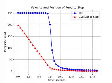
In graphical form
feedtostopVprofile.png
Really would have liked more detail around 6-7.5 seconds, but it's telling me that I have basically synthesized the sigmoidal function.
Now I have to make it stop sooner. Too slow! But it's a start, and a very good one at that.
 
RE: data logging of serial output
This is one of the many issues trying to use the monitor output as a terminal; other problems with monitor that affect my work are:
  • not understanding \r vs. \n (output without a line feed)
  • print overhead seriously limits fast output, and timing of main program
  • sharing data out and programming creates issues with both because of needing to disconnect/reconnect
My standard solution on nearly all boards is to use the hardware port instead. This addresses all of these problems, with output directed to a terminal program on a 2nd USB port (Teraterm on Windows; Serial on Mac). Fast, keeps connection, leaves program port free; can do single-line display output... and the terminal programs all have logging built in.

Sometimes I still want to print to the other port, and so to select one or the other, I use two flags and a custom 'print'.
It looks like this:

// destination print flags
uint16_t CONSOLE_FLAG = 0;
uint16_t HWSERIAL_FLAG = 1;


char msg[60] = "\0";

...

void echo(String msg) {
// general fctn to print a string, routed to various ports depending on global flags
if (HWSERIAL_FLAG) Serial1.print(msg);
if (CONSOLE_FLAG) Serial.print(msg);
}

// usage examples
echo("hello \n);

echo(5.67);

// for formatted outputs

sprintf(msg, " %6.3f, %6.3f, %6.3f, \t%04u \n", val1, val2, val3, u_val4);
echo(msg);
(oops; correction: flags should be bool, not uint16_t)
 
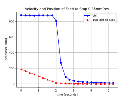
Running a little faster at 0.35mm/rev we get the following curve which shows the sigmoidal function better. I reduced the time gate to 250ms, can see the velocity fall off in the beginning better. Kind of like an s, which is what I wanted.
f2s_0p35mm400RPM.png
Well to close this out, learned not to take too much data. Can't get too greedy. This tells me enough that things are as designed (desired). For what it is worth, the distance to stop was derived from the actual position on a glass encoder scale. I used TeensyEncoderTool to read the scale and determined the distance to stop by subtracting from a previously set stop point.
 
I think I need to revisit this. I read about using usbserial, but I am confused. In the Arduino IDE Tools > USBtype, I need to state dual serial? If so, do I need a physical second cable? A FTDI 3.3V cable? Connecting to USB on a Mac. I could connect to a USB3 hub.

I'd like a separate channel to spool out some timing data, and I don't want it pumping in to the IDE.

So how is this done SW wise and physically? Writing to Serialx.printf? I could use TX3-TX6, TX8. The other pins (TX1,2,7) are used.
Is there a separate cable needed? This is not clear to me. If a separate cable, what pins do I connect to?

Or do I use the USBHost? I don't think I need anything fancy, I just need to spool out some data, like the 32bit cycle counter, when an event happens, and some parameter values at that time.

I will use a C or Python program to grab the data and plot it. Or just a terminal capture program, and process it later. Due to the multiple ISR's, I need to figure out what order things are executing. I may have to change my ISRs, but I have no motivation to do so, if there's really not an issue.

Edit:
Ok. Forget all of the above.

The real question I have is about USBSerial1. How do you connect to it? I think I know how to write to it. But what do I connect to on the other end? Is it present on the same physical USB cable that connects to the USB at the end of the Teensy? And Arduino IDE doesn't connect to USBSerial1, only "USBSerial"? I have never seen an explanation of this.
 
Last edited:
It just makes the Teensy act as two individual USB serial devices instead of one. The PC should show two serial ports; Arduino IDE serial monitor will connect to one as usual, and you can connect a comms program (or your C/python logger) to log the other one. On the Teensy software side the additional port is named "SerialUSB1".
 
It just makes the Teensy act as two individual USB serial devices instead of one. The PC should show two serial ports; Arduino IDE serial monitor will connect to one as usual, and you can connect a comms program (or your C/python logger) to log the other one. On the Teensy software side the additional port is named "SerialUSB1".
Finally got something to work. However, the use of SerialUSB1 totally screws up IDE2, at least my version. Once you use SerialUSB1, the IDE automatically switches to it and it won't switch back to Serial. I don't want to see SerialUSB1 on the IDE, only on my data logger. However, if I close the IDE, and open TyCommander, I can get it to work. Definitely cumbersome and slows down the work process.
 
Back
Top