S/pdif

Status
Not open for further replies.
I checked the status bits, and keeping everything 0 is what we need.
This boils down to: 44.1 kHz, no copyright, 1000ppm clock.
I do not have luck with the raspi code. When testing with all zeros as the input, I see
Code:
./spdif-encoder < /dev/zero | hexdump
0000000 cccc 00cc cccc cccc cccc 00cc cccc cccc
I cannot recognize the preamble in there.
 
perhaps some raspberry trickyness..
/* BCM2835-ARM-Peripherals.pdf:
* "Note that data is always serialised MS-bit first. This is well-established
* behaviour in both PCM and I2S."
*
* pcm_iec958.c says that preamble is at LSB ... Because of this, the bit ordering
* is reversed here while performing bmc encoding..
*/
There are 8 bits zero... hm.
 
I think I got it, only tested on PC.
Code:
/* This code is free to use */
/* Kire Pudsje, May 2015 */
#include <stdio.h>
#include <stdint.h>
#include <arpa/inet.h> // htonl

// table assumes previous state is 0, use bitwise invert of values otherwise
const uint16_t bmc_lookup[] = {
        0xcccc, 0xcccd, 0xcccb, 0xccca, 0xccd3, 0xccd2, 0xccd4, 0xccd5,
        0xccb3, 0xccb2, 0xccb4, 0xccb5, 0xccac, 0xccad, 0xccab, 0xccaa,
        0xcd33, 0xcd32, 0xcd34, 0xcd35, 0xcd2c, 0xcd2d, 0xcd2b, 0xcd2a,
        0xcd4c, 0xcd4d, 0xcd4b, 0xcd4a, 0xcd53, 0xcd52, 0xcd54, 0xcd55,
        0xcb33, 0xcb32, 0xcb34, 0xcb35, 0xcb2c, 0xcb2d, 0xcb2b, 0xcb2a,
        0xcb4c, 0xcb4d, 0xcb4b, 0xcb4a, 0xcb53, 0xcb52, 0xcb54, 0xcb55,
        0xcacc, 0xcacd, 0xcacb, 0xcaca, 0xcad3, 0xcad2, 0xcad4, 0xcad5,
        0xcab3, 0xcab2, 0xcab4, 0xcab5, 0xcaac, 0xcaad, 0xcaab, 0xcaaa,
        0xd333, 0xd332, 0xd334, 0xd335, 0xd32c, 0xd32d, 0xd32b, 0xd32a,
        0xd34c, 0xd34d, 0xd34b, 0xd34a, 0xd353, 0xd352, 0xd354, 0xd355,
        0xd2cc, 0xd2cd, 0xd2cb, 0xd2ca, 0xd2d3, 0xd2d2, 0xd2d4, 0xd2d5,
        0xd2b3, 0xd2b2, 0xd2b4, 0xd2b5, 0xd2ac, 0xd2ad, 0xd2ab, 0xd2aa,
        0xd4cc, 0xd4cd, 0xd4cb, 0xd4ca, 0xd4d3, 0xd4d2, 0xd4d4, 0xd4d5,
        0xd4b3, 0xd4b2, 0xd4b4, 0xd4b5, 0xd4ac, 0xd4ad, 0xd4ab, 0xd4aa,
        0xd533, 0xd532, 0xd534, 0xd535, 0xd52c, 0xd52d, 0xd52b, 0xd52a,
        0xd54c, 0xd54d, 0xd54b, 0xd54a, 0xd553, 0xd552, 0xd554, 0xd555,
        0xb333, 0xb332, 0xb334, 0xb335, 0xb32c, 0xb32d, 0xb32b, 0xb32a,
        0xb34c, 0xb34d, 0xb34b, 0xb34a, 0xb353, 0xb352, 0xb354, 0xb355,
        0xb2cc, 0xb2cd, 0xb2cb, 0xb2ca, 0xb2d3, 0xb2d2, 0xb2d4, 0xb2d5,
        0xb2b3, 0xb2b2, 0xb2b4, 0xb2b5, 0xb2ac, 0xb2ad, 0xb2ab, 0xb2aa,
        0xb4cc, 0xb4cd, 0xb4cb, 0xb4ca, 0xb4d3, 0xb4d2, 0xb4d4, 0xb4d5,
        0xb4b3, 0xb4b2, 0xb4b4, 0xb4b5, 0xb4ac, 0xb4ad, 0xb4ab, 0xb4aa,
        0xb533, 0xb532, 0xb534, 0xb535, 0xb52c, 0xb52d, 0xb52b, 0xb52a,
        0xb54c, 0xb54d, 0xb54b, 0xb54a, 0xb553, 0xb552, 0xb554, 0xb555,
        0xaccc, 0xaccd, 0xaccb, 0xacca, 0xacd3, 0xacd2, 0xacd4, 0xacd5,
        0xacb3, 0xacb2, 0xacb4, 0xacb5, 0xacac, 0xacad, 0xacab, 0xacaa,
        0xad33, 0xad32, 0xad34, 0xad35, 0xad2c, 0xad2d, 0xad2b, 0xad2a,
        0xad4c, 0xad4d, 0xad4b, 0xad4a, 0xad53, 0xad52, 0xad54, 0xad55,
        0xab33, 0xab32, 0xab34, 0xab35, 0xab2c, 0xab2d, 0xab2b, 0xab2a,
        0xab4c, 0xab4d, 0xab4b, 0xab4a, 0xab53, 0xab52, 0xab54, 0xab55,
        0xaacc, 0xaacd, 0xaacb, 0xaaca, 0xaad3, 0xaad2, 0xaad4, 0xaad5,
        0xaab3, 0xaab2, 0xaab4, 0xaab5, 0xaaac, 0xaaad, 0xaaab, 0xaaaa
};

// On the teensy, this is just a single assembly function
uint32_t rbit(uint32_t v)
{
        uint32_t r = 0;
        for (int i = 0; i < 32; i++) {
                r = (r << 1) | (v & 1);
                v >>= 1;
        }
        return r;
}

inline uint32_t parity(uint32_t v) __attribute__((always_inline));
inline uint32_t parity(uint32_t v)
{
        v ^= v >> 1;
        v ^= v >> 2;
        v = (v & 0x11111111ul) * 0x11111111ul;
        return (v >> 28) & 1;
}

static void inline bmc_encode(uint32_t *dest, uint16_t sample, uint16_t preamble) __attribute__((always_inline));
static void inline bmc_encode(uint32_t *dest, uint16_t sample, uint16_t preamble)
{
        uint32_t bmc1, bmc2, bmc3, val;
        val = rbit((sample << 4) | (parity(sample) << 23));
        bmc1 = bmc_lookup[(val >> 24) & 0xff];
        dest[0] = (preamble << 16) | (bmc1 & 0xffff);
        bmc2 = bmc_lookup[(val >> 16) & 0xff] ^ -(bmc1 & 1);
        bmc3 = bmc_lookup[(val >> 8) & 0xff] ^ -(bmc2 & 1);
        dest[1] = (bmc2 << 16) | (bmc3 & 0xffff);
}

int main(void) {
    int cnt = 1;
    bool left = true;
    uint16_t sample, preamble;
    uint32_t dest[2];
    while (fread(&sample, 2, 1, stdin))
    {
        cnt--;
        if (left) {
            if (cnt == 0) {
                cnt = 192;
                preamble = 0xe8cc;
            }
            else
                preamble = 0xe2cc;
        }
        else
                preamble = 0xe4cc;
        bmc_encode(dest, sample, preamble);
        left = !left;

        // flip because of byte order when writing to disk
        dest[0] = htonl(dest[0]);
        dest[1] = htonl(dest[1]);
        fwrite(dest, 8, 1, stdout);
    }
    return 0;
}
Code:
./spdif < /dev/urandom | hexdump -C
 
Last edited:
Sorry, you are right. There was a small mistake, I had 192 L+R frames, seems 192 is the total number of frames, code was adjusted.
 
Just as an interesting idea, there is another TOSLink optical audio protocol out there called ADAT.

It is 12.288 Mbit/s which is a challenge but would allow 8 channel audio output with a teensy if you use an ADA8200 but perhaps the most interesting thing is that the ADA8200 supports an external word clock from either the ADAT signal or a BNC input, so if you weren't able to do exactly 12.288Mbit/s it may not matter.

When SPDIF is working, I may take a look at whether I can use the same code to generate ADAT (it has a different clock and signalling scheme but I'd imagine the teensy peripheral usage would be similar).
 
@Frank B, Unless you are using pure synthetic waveforms, you cannot use 44100. With the audio shield it was possible, but the Teensy ADC clock needs to be an integer division of the system clock. 44118 is the closest. An escape would be to use 48000, which is a pure integer division of the system clock.
As said earlier, the 44118 is within specifications of the S/PDIF standard (1000 ppm)
 
Ok, you're right, the ADC I have not considered.

Too bad. We are now 45 Hz below the exact frequency.
144MHz FRACT: 1 DIV: 50 FREQ: 5647058.82 ERR:-45.18
120MHz FRACT: 3 DIV: 84 FREQ: 5647058.82 ERR:-45.18
96MHz FRACT: 0 DIV: 16 FREQ: 5647058.82 ERR:-45.18
72MHz FRACT: 3 DIV: 50 FREQ: 5647058.82 ERR:-45.18
48MHz FRACT: 1 DIV: 16 FREQ: 5647058.82 ERR:-45.18
16MHz FRACT: 5 DIV: 16 FREQ: 5647058.82 ERR:-45.189
(dont subtract 1)

But if this is within the spec, it'll be ok.
 
Actually, I now left my clock at 11.29 MHz, since apparently the minimum bit clock divider is 2 (reg value 0).
 
As said earlier, the 44118 is within specifications of the S/PDIF standard (1000 ppm)
from what I remember, however, this does not guarantee the sync between two devices, after a bit of time with excessive jitter they are no longer in sync.
 
I do not know what Frank's intentions are, but I just want to hook it up to my amplifier, so syncing between multiple inputs is not an issue for me.
I assume here that my amplifier has a PLL to recover the clock, and it is not a hardwired clock rate with sample skip synchronization.
 
Last edited:
Oh, I see... 64 encoded bits per sample. Hmmm... should be possible somehow. Will play with the audio lib side when those PCBs and connectors arrive.
 
This is how I got this far.
Still trying to convince the I2S module to output the correct number of bits without gaps, so not fully functional yet.
It is already integrated in the audio lib. Like I said in one of my first posts, only slight modifications needed to output_i2s.

Edit: Now starting to think the DMA copying only does 16 bits.

Indeed, but that is not all.
Code:
        dma.TCD->SOFF = 4;
        dma.TCD->NBYTES_MLNO = 4;

Edit2: I think I have the stream working. Now I need to check if audio is actually coming out.
Also I think it can now still be used together with the audio shield, where the audio shield can only be used as input.
This also allows for exact 44100 kHz sampling. But first: get it working.
 

Attachments

  • output_spdif.zip
    5.5 KB · Views: 509
Last edited:
I need a cinch output. But optional toslink is great. I saw some some example circuits somewhere, but they were TTL, not 3.2V.

Regarding IS2, the best format would be 32 Bits per channel, LSB first. This is very close to the spdif format.
 
OK now the file with the right bitstream (I think).
I now use 16 bit DMA copying and also 16 bit output from the I2S module. I know it is very ugly but it seems to do the trick for now.
I had to add ugly __REV(__REV16(...)).
The __REV16() is I think needed due to the 16 bit copying of DMA.
But also the byte order seems reversed, hence the __REV(). Bit order however is OK.

I cannot get any sound out of my amplifier yet. Either the bitstream is still wrong, or I cannot get enough light in the TOSLINK cable. (I only have a 15 meter version, which is on the long side). I tested with the LED on the teensy itself and also a TOSLINK LED module rescued from an old CD-player. But this was made for 5 volt and I cannot access the internal resistor.

Can anybody with a logic analyzer provide me with an example of a S/P-DIF stream, so that I can verify my data? I do have a bus-pirate, but the signals are too fast for it.
 

Attachments

  • output_spdif_v2.zip
    5.6 KB · Views: 268
OK now the file with the right bitstream (I think).
I now use 16 bit DMA copying and also 16 bit output from the I2S module. I know it is very ugly but it seems to do the trick for now.
I had to add ugly __REV(__REV16(...)).
The __REV16() is I think needed due to the 16 bit copying of DMA.
But also the byte order seems reversed, hence the __REV(). Bit order however is OK.

I cannot get any sound out of my amplifier yet. Either the bitstream is still wrong, or I cannot get enough light in the TOSLINK cable. (I only have a 15 meter version, which is on the long side). I tested with the LED on the teensy itself and also a TOSLINK LED module rescued from an old CD-player. But this was made for 5 volt and I cannot access the internal resistor.

Can anybody with a logic analyzer provide me with an example of a S/P-DIF stream, so that I can verify my data? I do have a bus-pirate, but the signals are too fast for it.

Perhaps we can get rid of some of the _REV later, with reversing the table and the rest.
I have a cheap 20MHz LA (should be ok for 5.6 MHz) , but unfortunately I will be the next few days on the road, so i can't do any measuring before friday.
Are you sure, that your 11MHz clock is ok ? How do you transfer the data, with doubling every bit or gaps between them ? As i understood it, we need 5.6 MHZ, not more, and a continous datastream, least significant bit first.
Regarding the light, I read that best works a 660 nm LED. It depends on the receiving-side how sensitive it is for other colors.
 
Last edited:
When watching on an oscilloscope, the stream seems like I want it to be, no gaps and the proper frequency. You are right, the __REV's are temporary. Also the 16 bit copying and outputting should be changed to proper 32 bit versions. But I first would like to hear some output.
This weekend I will grep a proper 5V buffer with sufficient speed, to properly steer my TOSLINK LED.
 
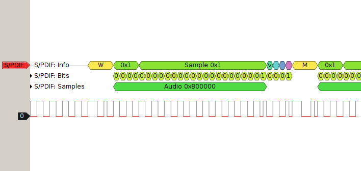
Not measured, but a "Screenshot" from sigrok. I think this helps a bit.
pulseview_spdif.jpg


http://sigrok.org/wiki/Protocol_decoder:Spdif

I hope that I find time for this on sunday....


Edit:
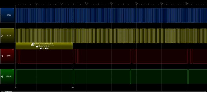
Screenshot of the preambles only, looks ok so far.
spdif1.jpg
Currently, i've configured I2S & DMA for 8-Bit, this makes the whole thing a easier.
The LR-Clock is synced to the preambles.
 
Last edited:
Success!!

Success !!
Yeah :)

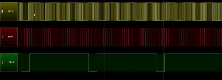
I have a stereo 1-khz "beep". Not from the audiolib, but it is the proof that the teensy is able to output SPDIF :)
I took a bright white LED (had no red LED in stock that was bright enough) and a TOSLINk cable.

This is the best 1000Hz beep I have ever heard ;-)

The rest is.. a "todo", but the main problems are solved now. The "connection" to the Audio-Library is missing, but that's not too complicated.
I think, that i can upload (GITHUB) a first working version in the next days.

spdif_beep.jpg
 
Last edited:
@Paul,
i never used DMA and I2S at this Level; and have only little knowlage about it (what is a "minor loop"?)

Currently I use the 16-Bit configuration from the I2S-output (Audiolib)
Better would be the following (i tried, but had no success):

There is a buffer:
DMAMEM static uint8_t SPDIF_tx_buffer[192 * 2 * 2 * 4];

I want to output it as 32 Bit values (currently 16)
We don't need any clock-signals, but for debugging it is good to configure the LRCLK as a sync-signal every 64 bit (this is a spdif-channel ) - i managed to do this for the current 16 bit output.
(2 * 64 Bit (=2 channels) are a "Frame", 192 "Frames" a "Block" - the tx_buffer from above is a whole block)

The DMA & I2S config needs to be changed to output the raw 32 Bit data from the buffer continously, with "I2S_TCR4_MF" not set (->LSB first)
Can you help ?
 
Last edited:
Can you help ?

Yes, but probably can't do very much until next week when I have all the hardware.

My purple PCB arrived this weekend. I have not soldered it yet, but I will soon. The connectors arrived from Digikey quite some time ago.

I ordered a TOSLINK to RCA audio adaptor and an optical cable on Amazon. Their shipping info says it will arrive on June 6 (yeah, I used the free but slow shipping, and Amazon took several days before shipping it... I think they intentionally delay if you don't pay for their "prime" service). It's a UPS tracking number. I do not believe UPS will really deliver on Saturday. Usually only postal mail arrives on the weekend. It's likely I will get it on Monday, June 8.

I could look at the waveform on my oscilloscope, but that would be very difficult to know if it's really working.
 
Last edited:
Status
Not open for further replies.
Back
Top