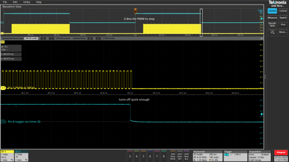
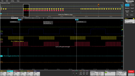
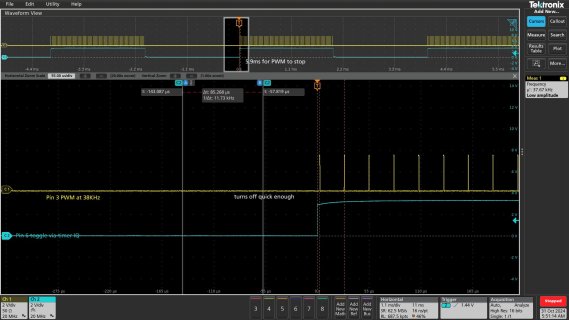
Good. Will wait for the code before trying to make sense of that scope screenshot.
But in the meantime, to try answering these latest question.
As with all microcontrollers, you have 3 basic ways to do this sort of thing.
1: bitbanging with tight loops
2: bitbanging with interrupt routines
3: leverage special timer hardware
If you go with bitbanging, use digitalWriteFast(pin, value). If the pin is a const and value is HIGH or LOW (both inputs are known to the compiler as constants at compile time) using digitalWriteFast() always compiles to a direct register write. ARM architecture has a ST instruction which depends on 2 registers being loaded with the address and the value to write. For tight loops and relatively simple code the compiler will usually pre-load those registers, so digitalWriteFast() often involves just the single ST instruction. But in a worst case it might involve some other instructions to load the registers ST needs. If you really care about those details, the best thing you can do is check the generated assembly code. It gets written as a .lst file in the temporary folder where Arduino compiles your program. In Arduino IDE, click File > Preferences (or Areduino IDE > Settings if using MacOS) and turn on verbose output during compile. Then you can see the compiler commands and look for the full pathname of the temporary folder. On Windows and MacOS it's usually inside a hidden folder, but once you know the full pathname you can use the tools of those platforms. On Linux it's usually in a folder inside /tmp.
If you go with the interrupt approach, you might try using
IntervalTimer.
It sounds like you really want to just access the hardware directly and not use any of the Arduino API or core library functions. You can do that. All the hardware registers are available to use from your program, with the names as published in the reference manual. Download if from the Teensy 4.1 product page. Just click or scroll down to "Technical Information" and it's the first document in the list. You can also get it from NXP's website, but they require registration. The PJRC copy it just a single click for the PDF, and ours has annotations so you can quickly see which pins and other details on Teensy correspond to NXP's rather cryptic pad naming.
But to be frank, if you're just going to do bitbangng, unless you want to toggle many pins at once you're probably just going to waste a lot of time. Just using digitalWriteFast and IntervalTimer will give you access to the native hardware.
You definitely do need to dive into the reference manual if you decide to go with route #3. You'll probably want to focus on the FlexPWM timers, which are chapter 55 stating on page 3091. The good news in FlexPWM is incredibly capable. These timers clock at 150 MHz when the CPU runs at 600 MHz, so assuming you don't prescale the clock you'll get 6.7ns timing resolution. While that's 1/4th the speed of the CPU, the timers generally give results that are independent of software latency like interrupts or bus usage by DMA-based peripherals (eg, USB). The bad news is so much hardware capability comes a lot of info to read and a lot of registers to digest.
You might look at the
comments in pwm.c starting on line 101. But generally speaking, the
website documenation about PWM doesn't feature a deep dive into the low-level details of the hardware. It's generally meant to allow Arduino-style access without needing to worry about those low level details. Reading the actual code really is the way to figure out what the APIs are actually doing. A lot of effort has gone into keeping that code compact and relatively to read, using the actual register names as documented in the referece manual (eg, not using extra abstraction layers which are supposed to make code easier to read but usually just end up adding a lot of extra complexity to unravel to the actual hardware accessed).


