SPI and Serial communication not working on teensy 4.x

Zter

Member
Hello everyone.
For one of my projects, I need to get the measurements of several accelerometers, at precise time intervalls, and log the data obtained on an SD card.
As I want the sampling rate to be as high as possible, I choosed SPI working accelerometers, the LSM6DSOX IMU, and Bought brand new teensy boards to run the programs (I have both the 4.0 and 4.1).
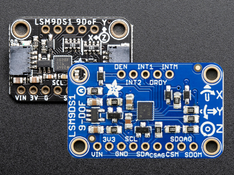
I don't use specialised libraries as I want to give the most appropriate filtering parameters for my accelerometers, and want to be able to add a 9-DOF IMU (LSM9DS1) to the system, I also use the legacy IDE, the new IDE doesn't work on my laptop (less than a year old, but after 10 minutes of loading without anything, I gave up).

To do my early tests and make bit by bit my programs I first started with the teensy and an accelerometer.
My connections :
sensor <-> teensy
Vin <-> 5V (regulated by the adafruit breakout board)
Gnd <-> G
Scl (Sck) <-> 13
Sda (DI) <-> 11 (MOSI)
DO <-> 12 (MOSI)
CS <-> 10

Code:
#include <SPI.h>
const byte CS_ax = 10;
const byte who_reg = 0x0F;
const byte READ = 0b10000000;

//bool read_rq;
//bool req_done = false;
byte who;

void setup() {
  // put your setup code here, to run once:
  pinMode(LED_BUILTIN,OUTPUT);
  pinMode(CS_ax, OUTPUT);
 
  digitalWrite(CS_ax,HIGH);
  digitalWrite(LED_BUILTIN,LOW);
  Serial.begin(9600);
  SPI.begin();
  //SPI.beginTransaction(SPISettings(1000000,MSBFIRST,SPI_MODE3));
  //SPI.endTransaction();
  SPI.setBitOrder(MSBFIRST);
  SPI.setDataMode(SPI_MODE0);
}

void loop() {
  who = read_1_reg(CS_ax,who_reg);
  Serial.println(who,BIN);
  delay(1000);
  // put your main code here, to run repeatedly:
 
}
byte read_1_reg(byte CS,byte adress){
  int result;
  // LSM9DS1 expects the read order on the first bit,
  //as the registers adresses begin by 0, we add the corresponding read bit
  adress = adress | READ;
  digitalWrite(CS, LOW);
  // send the device the register you want to read:
  SPI.transfer(adress);
  // send a value of 0 to read the first byte returned:
  result = SPI.transfer(0x00);
  digitalWrite(CS, HIGH);
  return (result);

I have two issues :
1) the SPI communication doesn't work : I tried to check the contents of the 0x0F register (WHO_AM_I), and it always returns a 0, instead of the expected answer : 01101100, the programs works flawlessly with an arduino uno and a levelshifter in beetween (5V MCU, 3.3V sensor).
It SHOULDN'T be an issue of SPI mode as my sensor is designed to work either with mode 0 or mode 3 (see LSM6DSOX datasheet)

2) The Serial interface is full of glitches :
in port selection , if I select teensy port COMX (Teensy 4.x) (X being 4 for the 4.0 and 7 for the 4.1 board) the COM port is always busy and the serial monitor can't be oppened
if I select Serial port COMX (Teensy 3.1/3.2) I get a little error message at each end of programming, the issue being that I need to always close the serial monitor elseway I get big warnings

I should explain that switching to a teensy board seemed a logic choice as it's way faster, has several SPI interfaces, works in 3.3V (no level-shifting required) and more compact than an UNO or other arduino boards, but if I can't get my programs runnning, I will really have wasted 80€ for nothing (not to mention being stuck with a MCU too slow for my project)
 
SPI absolutely works on Teensy. That looks a lot like reading / writing registers for InvenSense sensors as well (i.e. masking with 0x80 to read).
1. Recommend using digitalWriteFast instead of digitalWrite for toggling the CS line.
2. Also recommend using beginTransaction and endTransaction in the read_1_reg function.
3. The Teensy 4.1 is so fast that sometimes I need to add delayNanoseconds to get things to work.

Here's an example of my ReadRegister function for the InvenSense IMUs:

Also, try it with just one device on the SPI bus. Once you get that working, add more devices. Typically, with multiple devices, you'll need pullup resistors to pull the CS lines high or you'll need to initialize each CS line and pull high in software using digitalWrite before you start trying to talk with any of the devices.
 
My connections :
sensor <-> teensy
Vin <-> 5V (regulated by the adafruit breakout board)
Gnd <-> G
Scl (Sck) <-> 13
Sda (DI) <-> 11 (MOSI)
DO <-> 12 (MOSI)
CS <-> 10
Are you using this board?
If so, connect the sensor board Vin pin to the Teensy 3V3 pin, as described here.
Luckily, the DO/MISO pin from the sensor board is not level-shifted to the sensor board Vin voltage, so your Teensy will be OK for now.

Paul
 
If you look at this Arduino Library for the L6DSOX you will see what @brtaylor and @PaulStoffregen is recommending. It illustrates the typical way of working with SPI devices:

or you'll need to initialize each CS line and pull high in software using digitalWrite before you start trying to talk with any of the devices.
Code:
pinMode(_csPin, OUTPUT);
    digitalWriteFast(_csPin, HIGH);   //Lib has just digitalWrite
    SPI.begin()

I would also recommend making SPISettings a define that you an change after your #include <SPI.h>
Code:
SPISettings _spiSettings(1000000, MSBFIRST, SPI_MODE0);

1. Recommend using digitalWriteFast instead of digitalWrite for toggling the CS line.
2. Also recommend using beginTransaction and endTransaction in the read_1_reg function.

You need to use SPI.beginTransaction().

then your read function would look like:
Code:
byte read_1_reg(byte CS,byte adress){
  int result;
   SPI.beginTransaction(_spiSettings);
    digitalWrite(CS, LOW);
  adress = adress | READ;
  digitalWriteFast(CS, LOW);
  // send the device the register you want to read:
  SPI.transfer(adress);
  // send a value of 0 to read the first byte returned:
  result = SPI.transfer(0x00);
  digitalWriteFast(CS, HIGH);
  SPI.endTransaction();
  return (result);
}

and last note remember @brtaylor comment
The Teensy 4.1 is so fast that sometimes I need to add delayNanoseconds to get things to work.
 
Thanks for the advice.
SPI absolutely works on Teensy. That looks a lot like reading / writing registers for InvenSense sensors as well (i.e. masking with 0x80 to read).
1. Recommend using digitalWriteFast instead of digitalWrite for toggling the CS line.
2. Also recommend using beginTransaction and endTransaction in the read_1_reg function.
3. The Teensy 4.1 is so fast that sometimes I need to add delayNanoseconds to get things to work.

Here's an example of my ReadRegister function for the InvenSense IMUs:

Also, try it with just one device on the SPI bus. Once you get that working, add more devices. Typically, with multiple devices, you'll need pullup resistors to pull the CS lines high or you'll need to initialize each CS line and pull high in software using digitalWrite before you start trying to talk with any of the devices.
You need to use SPI.beginTransaction().
I tried yesterday night your propositions, but to no avail, I am consostently getting 0 as an answer instead of 01101100, I spend the next hour and a half coding a crude 4 channel oscilloscope on my Uno and the serial plotter, but the bandwidth is around 40 Hz, so not really usable and gave up for the night.
Are you using this board?
If so, connect the sensor board Vin pin to the Teensy 3V3 pin, as described here.
Luckily, the DO/MISO pin from the sensor board is not level-shifted to the sensor board Vin voltage, so your Teensy will be OK for now.

Paul
Thanks a lot, that was such a silly mistake of me to think about using a level-shifter with the UNO but to not check if powering the board with 5V would damage the teensy (all the more silly that I have spare accelerometers but not teensys)
This raises a question (about the LSM9DS1 board, an old version I bought two years and a half ago, which is level-shifted) If I power my sensor boards with 3.3V, won't the board's regulator struggle to keep it's output votage constant (as there wouldn't be enough available voltage drop), leading to noise in the power lines, giving noise in the measurements ? that was my reasoning behind powering 3.3V sensors with 5V.
Should I connect both the board's Vin and 3V pins to the Teensy's regulator?
If you look at this Arduino Library for the L6DSOX you will see what @brtaylor and @PaulStoffregen is recommending. It illustrates the typical way of working with SPI devices:


Code:
pinMode(_csPin, OUTPUT);
    digitalWriteFast(_csPin, HIGH);   //Lib has just digitalWrite
    SPI.begin()

I would also recommend making SPISettings a define that you an change after your #include <SPI.h>
Code:
SPISettings _spiSettings(1000000, MSBFIRST, SPI_MODE0);


then your read function would look like:
Code:
byte read_1_reg(byte CS,byte adress){
  int result;
   SPI.beginTransaction(_spiSettings);
    digitalWrite(CS, LOW);
  adress = adress | READ;
  digitalWriteFast(CS, LOW);
  // send the device the register you want to read:
  SPI.transfer(adress);
  // send a value of 0 to read the first byte returned:
  result = SPI.transfer(0x00);
  digitalWriteFast(CS, HIGH);
  SPI.endTransaction();
  return (result);
}

and last note remember @brtaylor comment
I tried that but still, same outcome, 0 instead of 01101100.
I didn't try yet the LSM6DSOX arduino library as it's custom-made for the arduino nano rp 2040, and I don't see in the example if I am using the SPI or I2C communication. Needless to say I don't care about the I2C communication in my application (it's way too slow) and I need to work with SPI.

I will try to visualise the communication lines on an oscilloscope to better understand what is going on, I will just need to wait for the next week to have it delivered at home.

Once again, thanks a lot for the advice, but I really think that I need to see the communication to really understand what is going wrong
 
I ordered one from adafruit for testing and will be here friday. Its about the only sensor I don't have
 
Should I connect both the board's Vin and 3V pins to the Teensy's regulator?

I re-read this thread but couldn't see which particular motion sensor board you have. Would be much easier to answer this sort of question if you could give a link to the product page if it's from a well-known site like Sparkfun or Adafruit. Or if it's a no-name board, whatever documentation exists (if any) or at least a photo would be better than try to bling guess.

A photo and/or clear diagram of your wiring between this board and Teensy might also help. Often times when the problem is a "simple" wiring mistake or a misunderstanding, just showing a couple photos from angles where we can see how the wires really connect can lead to spotting the problem. I'm not necessarily saying your wiring may be wrong... but I am saying you've got nothing to lose and (maybe) everything to gain by just showing us some photos of the actual wiring. We have a lot history on this forum of eventually figuring out what's wrong, and seeing photos usually makes everything go better.

And for a 3rd suggestion, and from your comment I'm getting the impression this one isn't something you'll like, you could at least for the sake of testing try installing libraries that claim to talk to this type of motion sensor and try running their examples (click File > Examples in Arduino IDE). Even if you don't want to actually use any libraries, just running their examples is so easy that you could at least get a quick confirmation if things work using that code.
 
This raises a question (about the LSM9DS1 board, an old version I bought two years and a half ago, which is level-shifted)
I guess you are referring to this board?
If I power my sensor boards with 3.3V, won't the board's regulator struggle to keep it's output votage constant (as there wouldn't be enough available voltage drop), leading to noise in the power lines, giving noise in the measurements ? that was my reasoning behind powering 3.3V sensors with 5V.
Yes, the board's regulator will have a small dropout but the LSM9DS1 chip will work from 2.4 - 3.6V.
Should I connect both the board's Vin and 3V pins to the Teensy's regulator?
No. The board's Vin is an input so that can be connected to Teensy's 3V3 regulator output pin. But the board's 3V pin is an output so leave that one unconnected.

Paul
 
I guess you are referring to this board?
was curious. I have the LSM9DS0 version of that board so I wired it up and used the Sparkfun LSM9DS0 library for testing. The wiring is as follows, directly from the sketch:

LSM9DS0 --------- Arduino
CSG -------------- 9
CSXM ------------- 10
SDOG ------------- 12
SDOXM ------------ 12 (tied to SDOG)
SCL -------------- 13
SDA -------------- 11
VDD -------------- 3.3V
GND -------------- GND

Worked right out of the box using a Teensy 4.1:
Code:
G: -5.65, -0.13, -1.79
A: -0.09, -0.01, 1.00
M: -0.20, 0.02, 0.30
Heading: 175.17
Pitch, Roll: -5.02, -0.48

G: -5.87, 0.70, -1.58
A: -0.09, -0.01, 1.00
M: -0.19, 0.01, 0.30
Heading: 176.74
Pitch, Roll: -5.07, -0.53

G: -5.45, 0.63, -1.69
A: -0.09, -0.01, 1.00
M: -0.19, 0.01, 0.30
Heading: 176.19
Pitch, Roll: -5.09, -0.47

As Paul said it would be good to know exactly what board is being used and what the wiring to the Teensy is. But as far as I can tell there is absolutely no issue with using these devices via SPI.

Mike

EDIT: This is the version of the library I am using:
 

Attachments

  • LSM9DS0.zip
    34.5 KB · Views: 20
Last edited:
Just as a further note I downloaded the Adafruit version of the LSM9DS0 library and ran the 2 example sketches using SPI and both worked no issues:

Code:
Accel X: -0.88       Y: -0.04       Z: 9.90      m/s^2
Magn. X: -27.50       Y: 7.24       Z: 41.44      uT
Gyro  X: -0.12       Y: 0.01       Z: -0.04      rad/s
Temp: 22.00 *C
**********************

Accel X: -0.90       Y: -0.04       Z: 9.83      m/s^2
Magn. X: -27.55       Y: 7.30       Z: 41.50      uT
Gyro  X: -0.11       Y: 0.00       Z: -0.04      rad/s
Temp: 22.00 *C
**********************

Accel X: -0.91       Y: -0.05       Z: 9.89      m/s^2
Magn. X: -27.58       Y: 7.27       Z: 41.53      uT
Gyro  X: -0.11       Y: 0.01       Z: -0.03      rad/s
Temp: 22.00 *C
**********************
 
About the sensor boards, I have and want to use :
The LSM9DS1 board from adafruit
The blue with wider pcb version
The LSM6DSOX board, also from adafruit

I will try the lsm9ds1 library tomorrow and post some pictures, if that works, I will then extract what I need for that 9-dof IMU and adapt it to the lsm6dsox (used as accelerometers). It shouldn't be that difficult to give the correct initialization parameters and read the appropriate registers. Thanks a lot for your pieces of advice
 
Be aware that these ST MEMS with their SPI and I2C interface options can cause trouble during initialization. More on that in this thread: https://forum.pjrc.com/index.php?threads/spi-help-moving-from-teensy-3-2-to-4-1.73318/page-2
The bottom line: if you fail to actively disable I2C mode after a power on reset, then the sensor chip will fall into I2C mode unexpectedly when /CS is high, MOSI pin is low and SCL goes high to low. That can happen for all sorts of reasons. Also if a sensor chip is the only one on that SPI bus. Which this one never is, because inside the package it is a sandwich of two physical sensor chips (one for accel/gyro, the other for the magnetics).
The T4 default SPI library that you use now has (had?) the bad habit of leaving the MOSI pin level at either high or low depending on what the level was at the last bit of a previous SPI interrogation. That may bite. Unless I2C mode disabling (via the I2C interface in I2C mode...) has been done after power on reset, before starting to access in SPI mode.
 
Just a quick update. I received my Adafruit LSM6DSO32 yesterday and just had a chance to test it out. Unfortunately they are out of stock of the X version. Using their LSM6DS library and hooking it up per:
All pins going into the breakout have level shifting circuitry to make them 3-5V logic level safe. Use whatever logic level is on Vin!
  • SCK - This is also the SPI Clock pin, it's an input to the chip
  • DO (Bottom) - this is the serial Data Out / Microcontroller In Sensor Out pin, for data sent from the LSM6DSOX, ISM330DHCX, or LSM6DSO32 to your processor.
  • SDA - this is also the Serial Data In / Microcontroller Out Sensor In pin, for data sent from your processor to the LSM6DSOX, ISM330DHCX, or LSM6DSO32
  • CS (Bottom) - this is the Chip Select pin, drop it low to start an SPI transaction. Its an input to the chip
works no issue:
Code:
Adafruit LSM6DSO32 test!
LSM6DSO32 Found!
Accelerometer range set to: +-8G
Gyro range set to: 2000 degrees/s
Accelerometer data rate set to: 104 Hz
Gyro data rate set to: 104 Hz
        Temperature 23.25 deg C
        Accel X: -0.03     Y: -0.26     Z: 9.97 m/s^2
        Gyro X: 0.34     Y: 0.22     Z: 0.02 radians/s

        Temperature 23.28 deg C
        Accel X: -0.02     Y: -0.26     Z: 9.99 m/s^2
        Gyro X: 0.00     Y: 0.02     Z: -0.01 radians/s

        Temperature 23.35 deg C
        Accel X: -0.02     Y: -0.26     Z: 10.00 m/s^2
        Gyro X: -0.00     Y: 0.02     Z: -0.01 radians/s

        Temperature 23.37 deg C
        Accel X: -0.05     Y: -0.24     Z: 10.02 m/s^2
        Gyro X: -0.00     Y: 0.02     Z: -0.01 radians/s

now using your basic code with the suggestions I mentioned:
Code:
#include <SPI.h>
const byte CS_ax = 10;
const byte who_reg = 0x0F;
const byte READ = 0b10000000;

SPISettings _spiSettings(1000000, MSBFIRST, SPI_MODE0);

//bool read_rq;
//bool req_done = false;
byte who;

void setup() {
  // put your setup code here, to run once:

  pinMode(CS_ax, OUTPUT);
  digitalWrite(LED_BUILTIN,LOW);
  Serial.begin(9600);


  digitalWriteFast(CS_ax, HIGH);   //Lib has just digitalWrite
  SPI.begin();

}

void loop() {
  who = read_1_reg(CS_ax,who_reg);
  Serial.println(who,HEX);
  delay(1000);
  // put your main code here, to run repeatedly:
 
}


byte read_1_reg(byte CS,byte adress){
  int result;
   SPI.beginTransaction(_spiSettings);
    digitalWrite(CS, LOW);
  adress = adress | READ;
  digitalWriteFast(CS, LOW);
  // send the device the register you want to read:
  SPI.transfer(adress);
  // send a value of 0 to read the first byte returned:
  result = SPI.transfer(0x00);
  digitalWriteFast(CS, HIGH);
  SPI.endTransaction();
  return (result);
}

I am seeing the following for WhoAmI id:
Code:
6C
6C
6C
6C
6C
6C
6C

Which is correct from their API for my device:
#define LSM6DSO32_CHIP_ID 0x6C ///< LSM6DSO32 default device id from WHOAMI
so the only thing that I can think of is somehow your wiring is off.

EDIT: I am currently using 1.59 beta 4 with IDE 2.2.2 nightly build.
 
Update :
Sorry for not being active during kast week, I was really busy because of work.
Firstly, a HUDGE thanks to mjs513 as now I have a reliable way to interface my lsm6dsox.
Secondly, I tried the program and got mixed results : it works well overall, but the communication glitches often, without any apparent reason
Thirdly, I tried with success to give the proper parameters to one accelerometer, thus I was able to get the measured acceleration
Fourthly, I tried connecting 4 accelerometers to the same board to test multipe adressing (just executing the same operation, but with a different CS) and I get glitches when trying to access acceleration, I will test each accelerometer separately and them retest the whole 8, I might be running into issues due to breadboard noise.

So I have two questions :
1) is there a way to decrease noise with pull-up resistors on communication lines ?
 
So I have two questions :
1) is there a way to decrease noise with pull-up resistors on communication lines ?
you may want to read through this:

Better SPI Bus Design in 3 Steps

Secondly, I tried the program and got mixed results : it works well overall, but the communication glitches often, without any apparent reason
Thirdly, I tried with success to give the proper parameters to one accelerometer, thus I was able to get the measured acceleration
Are you using the library or did you roll your own? When I used the library and did see any issues. Not sure what you mean by glitches.
 
In answer to question 1): no, pull-up will not help you out. Except maybe just after power on reset while SPI pins (which are also I2C on ST MEMS…) are still floating.
As mentioned in earlier post: unless I2C mode is actively disabled after ST MEMS power on reset, trouble with SPI interrogation will not go away. Disabling I2C must be done by setting a bit in a config register. Either using I2C or SPI. But if over SPI then one should not use T4 SPI library, but bit bang instead. See datasheet on which config bit that is. For yours it likely is two registers because your package contains 2 sensor chips, and both must be deactivated for I2C.

With CS high, an I2C START condition will be seen when the SDI(O) and SCK lines do what I2C START is. Unless there’s I2C STOP, the ST MEMS will refuse to listen to a SPI master. Your code, any T4 default SPI library code, and the T4 LPSPI hardware will keep doing that every now and then I’m afraid.

Another pitfall with T4 SPI and ST MEMS is bouncing on long clock wires. If the SPC wire is say >>50 cm long then echoes make one clock edge look as two, not only for the slave but even for the master. Teensy output pin config settings bandwidth (V/us), and hysteresis enabled may help somewhat, but in my case (2 meters) only way out was 100 ohms twisted pair and RS422 tranceivers for SPI clock distribution.
 
Last edited:
Indeed SPI bus to 8 devices can become a signal quality nightmare, especially if the wires are "long" and there is any substantial space between each signal wire and its return GND path.
 
IMG_20231212_220305.jpg


Color scheme :
Red : 3.3 V
Black/Grey/Brown : GND (I ran out of balacjk wires)
Blue/Orange : SCK
Green/White : MOSI
Yellow : MISO
The two exterior power rails are 3.3V power
The inner rails, from left to right
SCK, MOSI, MISO and a GND

I finally acheived acceleration reading on 4 sensors at the same time, I firstly tried all four aligned behind the teensy on a classic breadboard, before realizing that the two furthest didn't respond correctly.
It seemed to be due to some noise on the CS wires which were 20 cm long, instead of the 7cm ones used on the nearest ones.
So I switched to my double breadboard (on the photo) and I tested with two accelerometers, and added another, tested and added the last one
The SCK, MISO and MOSI lines are made thanks to the middle power rails.
I ran into moise issues on CS lines, as such each CS line (exept for the nearest one) is doubled with a ground wire to decrease noise, it's seems to work well, except that the nearest accelerometer output improper data (I should double it's CS line with ground).
I am still not interfacing 8 accelerometers simultaneously, but I think I am hitting the limits of the breadboard, I have still a working spi communication with several accelerometers, so it's a win.
I will try making an appropriate pcb to further test the whole communication, and I will add ground protection everywhere I can. I am still limited to single face pcbs, as I make them myself (there are some critical design aspects on the pcb which I don't want to publish or even leak). Thanks A LOT for all of your help on this journey, I will never have seen the end without you.
 
Last edited:
The SPC distribution is more critical than CS or MOSI or MISO.
But in your case, if you still use the code as in earlier posts, you also may have an SPI mode conflict, which manifests as a CS issue.
SPI mode 3 is what you should be using according to ST datasheet, mode 0 is what you might still use when this is still there:

SPISettings _spiSettings(1000000, MSBFIRST, SPI_MODE0);

Irrespective of that, without disabling I2C mode on all connected sensors after power on reset as step #1, (your sensors have that bit in CTRL4 (13h) and in CTRL9XL (18h) because it’s a 2 chips sandwitch) bit banging, problems will never fully go away… The whole Arduino idea of just re-using libraries that worked on other processor chips: forget it with these ST MEMS and Teensy4+.
 
Back
Top