Teensy 4.1 extra pins

Status
Not open for further replies.

Cotman

Member
Not sure if I have been looking in the wrong places but I am trying to find out how to get access to the extra 13 pins on the reverse of the 4.1 board.
I have looked at the schematics and can clearly see how to pick up on the 7 lines that terminate at the extra ram/flash pads but I cannot see where is the right place to pick up on the 6 lines that go to the SD card?

The project I am working on requires 42 pins for digital I/O, 7 pins for display/touch and 2 for I2C. Also I would like to add some LED mode indicators if I have the option.
Without disassembling the Teensy, I would imagine the only way to get to the SD pins (42-47) is to use a card that fits in the micro SD slot and brings out the pins:

Alternatively for the digital inputs or outputs, use an I2C chip like the MCP23017 that allows you to connect 16 separate input/outputs per I2C device (3 address pins, so you can up to 8 MCP23017's on an I2C, or 128 inputs):
 
Last edited:
The project I am working on requires 42 pins for digital I/O, 7 pins for display/touch and 2 for I2C. Also I would like to add some LED mode indicators if I have the option.

Cotman:

I can't speak for the extra pins on the back of the T4.1, but the easiest way that I have used to successfully add a number of LED indicators (my TeensyMIMIPolySynth project https://forum.pjrc.com/threads/60690-queued-TeensyMIDIPolySynth?p=237404&viewfull=1#post237404 included 40 LEDs plus 2 7-segment displays) is to use the 74HC595 shift register chip (cascading as many as needed & connecting RCLK & SRCLK together...be aware that this induces a 1-bit delay into the data stream that needs to be accounted for). Adding the 74HC595 only uses two Teensy pins minimum (data & clock), or you can also use an additional pin to control the 74HC595 output enable if desired (I use this to PWM control the brightness of the LEDs).

Also, if any of your 42 digital I/O pins are being used as inputs & are being "sampled" (like pots or pushbuttons, for example), you might take a look at using the 74HC4067 16:1 analog MUX (works for both analog & digital inputs). This will allow you to optimize the use of fewer pins on the Teensy (again, my TeensyMIDIPolySynth uses these to very efficiently sample 48 pots & 42 pushbuttons)

Judicious application of these two additional pieces of hardware (if applicable) may eliminate the need for using the backside pins on the T4.1.

Good luck & have fun !!

Mark J Culross
KD5RXT
 
Last edited:
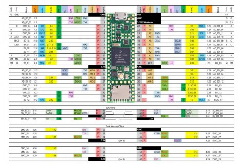
You can get to the back pins, But they are not all unique pins...
I have an XLS document plus PDF of some of the page up on github. But this print may show part of it for you.
screenshot.jpg
That is both chip patterns share the same IO pins, except for different chip select pins.

I have done a quick and dirty castellated board, which I extended the board by .5" and brought those signals plus the PGM, ON/OFF, VBat to outside pins to use as a test board.

Note: Also by default the 4.1 startup code will do some IO to these pins to try to determine if there are RAM and/or flash chips on it. I have suggested one way we can make that optional, but so far the code always runs at startup on a 4.1...
 
Thanks for all the replies.
I will already be using some MCP23017 for voltage switching.
I thought that might be the case with the SD card slot.
Kind of annoying that the ram/flash pins are played with at boot but not a deal breaker for me.

To explain my project better:
I am developing an IC tester for TTL/SRAM/DRAM/ROM/PROM/PAL devices upto 42 pins. I have to switch various voltages (5v/-5v/12v) and ground to various of the 42 pins depending on the device under test.
I want to use direct Teensy Digital pins in order to achieve testing into the Mhz range and to derive device timings which can highlight failing devices. The speed aspect is an absolute for the project as I can already test most of these devices using my Universal Programmer but it is very simple testing.
BTW My main hobby is repairing and maintaining old Arcade Game PCB's for the 70's through to the 90's. I have already developed an in circuit tester that works very well using an FPGA logic analyser but this needs a PC and the intention is to use the Teensy with a TFT and touchscreen as a standalone unit.
 
Status
Not open for further replies.
Back
Top