Teensy 4.1 NTP server

Some initial results

Good afternoon all,

Some early results:
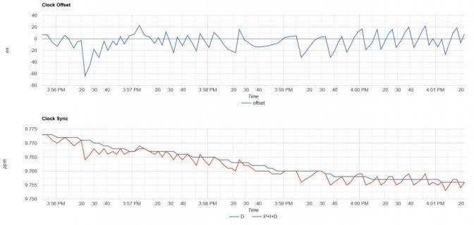
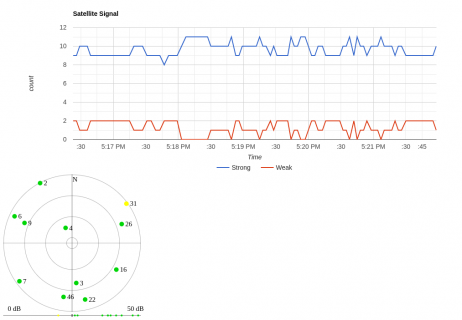
Screenshot 2021-05-21 160138.jpg
Screenshot 2021-05-21 160202.jpg

And the stats from the bottom:
Code:
PPS To GPS: 107 ms
millis() at PPS: 9376.972
millis() at GPS Timestamp: 9377079
millis() now: 9377.766
NTP time: 3830619824
IEEE 1588 counter at PPS: 2463559265
Offset between NTP/GPS times: 0.000000029 s
Estimate of NTP clock freq: 0.000009757 s/s
ChiSq fit of freq measure: 1.678
PID output: 9760 ns/s (ppb)
GPS lock Status: 3D
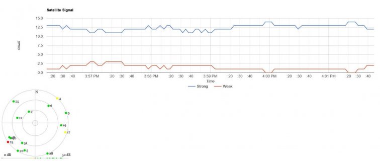
GPS Strong signals (> 25db): 14, Weak Signals (10db-24db): 0, No Signal (0db-9db): 1
GPS pdop=1.6, hdop=0.8, vdop=1.4

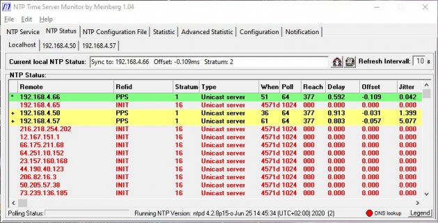
And Meinberg shows it as a valid peer available for synchronization.
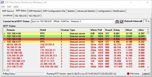
Screenshot 2021-05-21 160454.jpg

I should note that:
192.168.4.66 is the Teensy.
192.168.4.65 is a Chinese NTP server from the ePlace.
192.168.4.50 is an RPi NTP server.
192.168.4.57 is an RPi NTPSec server.

Why do I have four GPS NTP servers on my local network? Why not? hahaha

Thanks much,
Ben
 
I'd love to see your enclosure design, that sounds neat. I've been meaning to design a "shield" with a GPS module and an ethernet connector built in, but keep on getting distracted with other projects.

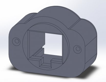
The enclosure is actually a recycled extruded aluminum enclosure from the ePlace that held a previous, failed project. The 3D printed part was a piece to hold the Teeny ethernet jack board - nothing really special, but here's a quick screen-grab just for giggles:
Screenshot 2021-05-21 161028.jpg

If anyone desires, I'll upload the source files. I can do STL, STEP, IGES, et cetera, just let me know.

The jack mounts with two screws into a 1" hole. I can drill nice round holes; squares are a lot more difficult. :)

Thanks much,
ben
 
GPS Strong signals (> 25db): 14, Weak Signals (10db-24db): 0, No Signal (0db-9db): 1

Those are some good GPS signals

192.168.4.66 is the Teensy.
192.168.4.65 is a Chinese NTP server from the ePlace.
192.168.4.50 is an RPi NTP server.
192.168.4.57 is an RPi NTPSec server.

Interesting that .65 claims a round trip time of 59 microseconds. I wonder if it's lying about the transmit time on the response. The RPIs and the Teensy seem to agree to the time within 100 microseconds and were all polled at around a minute of each other. Using a 1024 second interval, it's hard to tell if the .65 server is off by 500 microseconds or if the local time had just drifted by that much in 10 minutes.

Why do I have four GPS NTP servers on my local network? Why not? hahaha

I agree, I think there should be more GPS NTP servers.
 
The antenna I'm using is a cheap, magnetic-mount eBay special on a groundplane about a foot square, inside the house. I do have an external amplified GPS antenna that I split 8-ways with a non-amplified splitter, it's both better (better view of the sky) and worse (the splitter adds a lot of loss). In the past, the receiver that feeds the outdoor antenna with +5VDC for power failed, which took down *everything*, so I now keep two of the NTP servers on dedicated, magnetic-mount antennas.

I have my doubts about the Chinese NTP server. Apparently, it's a Telit GPS module feeding a fairly low-cost TI microcontroller based on a Cortex M4. There are a couple of photos of the unit opened up here: https://fc-ntp-100.toimii.fi/ It would not surprise me if the Chinese NTP server was doing something funky such as lying about transmit time. I've been keeping my eyes open for a "real" NTP server by Endrun, Brandywine, Spectracom, etc., but so far, none have come up at a price I'm willing to pay. My thought is that a "real" NTP server would be the reference to which I could compare all the others.

Totally in agreement - with GPS NTP being so low cost these days, there should be more of them out there. :)

Thanks much,
Ben
 
And some additional results!

Figured I'd follow up now that the Teensy NTP has had some time in its new enclosure. PLUS, I powered down the Chinese NTP Server (192.168.4.65) just for kicks. I do think it was somehow lying to me.

Screenshot 2021-05-24 172628.jpg
Screenshot 2021-05-24 172651.jpg
Screenshot 2021-05-24 172714.jpg

Code:
PPS To GPS: 104 ms
millis() at PPS: 273805.386
millis() at GPS Timestamp: 273805490
millis() now: 273805.702
NTP time: 3830884255
IEEE 1588 counter at PPS: 3169238425
Offset between NTP/GPS times: -0.000000025 s
Estimate of NTP clock freq: 0.00001024 s/s
ChiSq fit of freq measure: 3.940
PID output: 10237 ns/s (ppb)
GPS lock Status: 3D
GPS Strong signals (> 25db): 13, Weak Signals (10db-24db): 0, No Signal (0db-9db): 1
GPS pdop=2, hdop=0.9, vdop=1.7

I'm pretty happy! Fairly good agreement between the Teensy and the two RPi GPS/NTP servers. :)

Thanks much,
ben
 
Nice work.

Somewhat off topic, but if a PC is left connected and the goal is just an accurate teensy clock, then one can simplify with the use of the PC (with a ntp client on it) as an accurate timing source. For example, I use a once per second single byte from the PC to adjust the teensy audio clock. Which eliminates some obnoxious audio artifacts and buffer xruns.
 
Last edited:
Greetings all - dumb question time: on y'alls Teensy 4.1 NTP servers, does the RJ45 jack LED light up? (assuming you're using the PJRC ribbon header / RJ45 jack board) Mine does not and I'm wondering if I've got a cold solder joint or something like that...

thanks,
ben
 
The antenna I'm using is a cheap, magnetic-mount eBay special on a groundplane about a foot square, inside the house. I do have an external amplified GPS antenna that I split 8-ways with a non-amplified splitter, it's both better (better view of the sky) and worse (the splitter adds a lot of loss). In the past, the receiver that feeds the outdoor antenna with +5VDC for power failed, which took down *everything*, so I now keep two of the NTP servers on dedicated, magnetic-mount antennas.

Yeah, I'm also using the magnetic-mount antennas on a windowsill.

I have my doubts about the Chinese NTP server. Apparently, it's a Telit GPS module feeding a fairly low-cost TI microcontroller based on a Cortex M4. There are a couple of photos of the unit opened up here: https://fc-ntp-100.toimii.fi/ It would not surprise me if the Chinese NTP server was doing something funky such as lying about transmit time. I've been keeping my eyes open for a "real" NTP server by Endrun, Brandywine, Spectracom, etc., but so far, none have come up at a price I'm willing to pay. My thought is that a "real" NTP server would be the reference to which I could compare all the others.

LeoNTP is another low cost NTP server, and I've seen some good results from other people's tests of them.


jonr said:
Somewhat off topic, but if a PC is left connected and the goal is just an accurate teensy clock, then one can simplify with the use of the PC (with a ntp client on it) as an accurate timing source. For example, I use a once per second single byte from the PC to adjust the teensy audio clock. Which eliminates some obnoxious audio artifacts and buffer xruns.

Yup, NTP client will meet most everyone's needs these days. Of course, those NTP clients need to get time from somewhere, which is why I created an NTP server :) I'm also using it as one of the upstream sources of my cloud VMs which are part of the NTP pool, which serves time to everything from android phones, to other people's servers.

kd5byb said:
Greetings all - dumb question time: on y'alls Teensy 4.1 NTP servers, does the RJ45 jack LED light up? (assuming you're using the PJRC ribbon header / RJ45 jack board) Mine does not and I'm wondering if I've got a cold solder joint or something like that...

yeah, I get the green link LED that blinks on activity
 
yeah, I get the green link LED that blinks on activity

Very good. Just pulled my 4.1 out of the case and the green LED lights from an external supply when powered thru the Teensy end of the cable. Reflowed the solder joints on the pins and measured 150 ohms from the LED pin to the other side of the 150 ohm resistor (which was super hard to do, those resistors are tiny). Still doesn't work. Probably needs a reflow on the ethernet chip, but that's above my skill level so I'm just going to leave it alone and call it good as-is. :)

Thanks much,
ben
 
Awesome project!
Thanks for making it available. I've finally gotten it running with a ublox NEO-M8N-0-10 module and active antenna.

In settings.h
uncomment the #define GPS_USES_RMC
change the baud rate to GPS_BAUD 9600

and in GPS.cpp
change:
#define GPS_CODE_RMC "GPRMC"
#define GPS_CODE_GGA "GPGGA"

to:
#define GPS_CODE_RMC "GNRMC"
#define GPS_CODE_GGA "GNGGA"

Curious that the GPS_CODE... needed to be changed. Didn't see that posted by others using M8N? Maybe the modules 2.x firmware should be updated to 3.x?

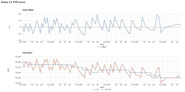
Not sure why but my Clock Sync count settles to 26.xxx ppm rather than others posted 8.xxx. As noted temperature is a big factor.

As you are no doubt aware the Teensy4.1 can be run at many CPU speeds. Your program seems to run fine even at the lowest 24MHz speed. Not sure what all the effects are but the PID seems to work just fine, maybe a little more overshoot. Probably the ntp responses will be worse.

With the lower speed -> power dissipation -> lower temperature variation, I have noticed a quieter Clock Sync count
600Mhz mine settles to 27 +-.020
24MHz 26 +-.005

In an unrelated program found that when the CPU speed speed is changed on the fly the internal temp sensor response tc is < .5 sec. Haven't tried yet on this program but I will and post some plots if anyone is interested. Perhaps the Clock cycle count could be smoothed by changing the CPU speed?

I would like to get a 10MHz signal output. Any thoughts on the best way to do this?
 
Not sure why but my Clock Sync count settles to 26.xxx ppm rather than others posted 8.xxx. As noted temperature is a big factor.


I would like to get a 10MHz signal output. Any thoughts on the best way to do this?

Every crystal is likely to have a different frequency offset (drift,ppm). The spec for the crystal specifies the expected range, e.g. +-20 ppm. FWIW, for my various Teensy 4s, here are measured drift values. As you noted, frequency can vary with temperature (post #15).

The Teensy 4 can generate 10mhz PWM (analogWriteFrequency()), but the accuracy will reflect the drift offset of the 24 MHz crystal. Here is a thread that discusses dithering the PWM compare register to "tune" the PWM frequency. You might also search forum for GPSDO. There is also a windows program (u-center) that configures u-blox GPSs and you can configure the GPS PPS output to run at 10MHz (GPS accurate).
 
Last edited:
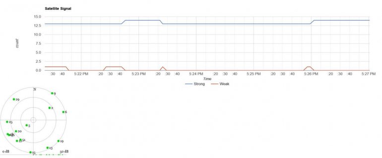
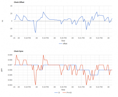
I had not been keeping track of developments; I only just saw the T4.1 NTP server code was updated to include the webserver with some plots and numbers. In case of interest here are my current results, with a rooftop antenna. My receiver is limited to the original US GPS constellation only, but the antenna position allows for reasonably good signal reception.

Code:
PPS To GPS: 347 ms
millis() at PPS: 2225.722
millis() at GPS Timestamp: 2226069
millis() now: 2227.004
NTP time: 3842900464
IEEE 1588 counter at PPS: 3955615440
Offset between NTP/GPS times: 0.000000012 s
Estimate of NTP clock freq: 0.000008906 s/s
ChiSq fit of freq measure: 0.224
PID output: 8907 ns/s (ppb)
GPS lock Status: 3D
GPS Strong signals (> 25db): 10, Weak Signals (10db-24db): 1, No Signal (0db-9db): 0
GPS pdop=1.8, hdop=1, vdop=1.5
 

Attachments

  • NTP-GPS-2021-10-10_17-22-47.png
    NTP-GPS-2021-10-10_17-22-47.png
    64.8 KB · Views: 113
  • SatSignal_2021-10-10_17-22-02.png
    SatSignal_2021-10-10_17-22-02.png
    57 KB · Views: 110
Last edited:
I'm trying to get the teensy-ntp.ino example to work with the Adafruit Ultimate GPS V3. The PPS is connected to T4.1 D35 but I can't get any coordinates on the output.

I've tried changing the setting as in msg #60 but still nothing.

On the CLI I get this :
Ethernet 1588 NTP Server
------------------------

netif status changed: ip 0.0.0.0, mask 0.0.0.0, gw 0.0.0.0
waiting for link
enet link status: up
netif status changed: ip 192.168.1.87, mask 255.255.255.0, gw 192.168.1.1

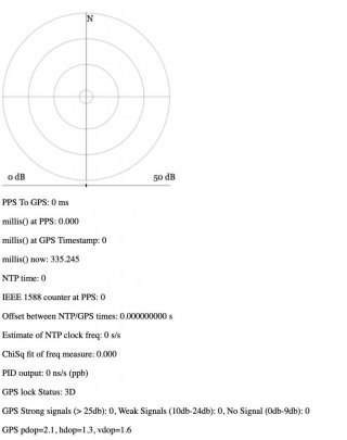
On the browser after a few seconds the GPS lock Status changes to 3D so I assume the Tx and Rx is wired correctly but everything else is blank.
NTP_GPS_state.jpg

Any idea on how to fix this ?
 
here is minimal GPS test sketch running with T4.1 and adafruit ultimate v3 GPS
Code:
// GPS Tx to  T4 pin 0 Rx,  PPS to T4 pin 35, 3v3 to Vin, GND to GND
void ding() {
  Serial.println("\nPPS");
}

void setup() {
  Serial.begin(9600);
  while (!Serial);
  delay(1000);
  attachInterrupt(35, ding, RISING);

  Serial1.begin(9600);
  while (Serial1.available()) Serial1.read();
}

void loop() {

  while (Serial1.available()) {
    char c = Serial1.read();
    Serial.print(c);
  }
}

you may need external antenna to establish and maintain fix.

Code:
PPS
$GPGGA,221016.000,xx01.3036,N,0xx12.4109,W,2,5,1.34,202.1,M,-32.1,M,0000,0000*65
$GPGSA,A,3,16,26,31,04,32,,,,,,,,1.61,1.34,0.90*0F
$GPRMC,221016.000,A,xx01.3036,N,0xx12.4109,W,0.70,154.20,031121,,,D*7B
$GPVTG,154.20,T,,M,0.70,N,1.30,K,D*3F

PPS
$GPGGA,221017.000,xx01.3036,N,0xx12.4107,W,2,5,1.34,202.3,M,-32.1,M,0000,0000*68
$GPGSA,A,3,16,26,31,04,32,,,,,,,,1.61,1.34,0.90*0F
$GPRMC,221017.000,A,xx01.3036,N,0xx12.4107,W,0.65,154.66,031121,,,D*72
$GPVTG,154.66,T,,M,0.65,N,1.21,K,D*39
 
Thanks for the code. The ding() is called.

I get the output ok.


PPS
$GPGGA,221922.000,51xx.2695,N,00004.5937,E,2,8,0.98,75.8,M,47.0,M,0000,0000*66
$GPGSA,A,3,29,25,12,31,32,04,02,26,,,,,1.55,0.98,1.21*0E
$GPGSV,3,1,11,29,81,137,31,31,62,276,49,25,55,094,32,49,30,173,28*7C
$GPGSV,3,2,11,02,27,048,22,26,27,283,43,12,22,093,23,32,10,222,38*7D
$GPGSV,3,3,11,18,10,170,20,04,06,339,25,20,06,072,16*4F
$GPRMC,221922.000,A,51xx.2695,N,00004.5937,E,0.02,55.24,031121,,,D*56
$GPVTG,55.24,T,,M,0.02,N,0.03,K,D*0F

PPS
$GPGGA,221923.000,51xx.2695,N,00004.5937,E,2,8,0.98,75.8,M,47.0,M,0000,0000*67
$GPGSA,A,3,29,25,12,31,32,04,02,26,,,,,1.55,0.98,1.20*0F
$GPRMC,221923.000,A,51xx.2695,N,00004.5937,E,0.02,55.24,031121,,,D*57
$GPVTG,55.24,T,,M,0.02,N,0.04,K,D*08

PPS
$GPGGA,221924.000,51xx.2695,N,00004.5937,E,2,8,0.98,75.8,M,47.0,M,0000,0000*60
$GPGSA,A,3,29,25,12,31,32,04,02,26,,,,,1.55,0.98,1.20*0F
$GPRMC,221924.000,A,51xx.2695,N,00004.5937,E,0.01,55.24,031121,,,D*53
$GPVTG,55.24,T,,M,0.01,N,0.03,K,D*0C

PPS
$GPGGA,221925.000,51xx.2695,N,00004.5937,E,2,8,0.98,75.8,M,47.0,M,0000,0000*61
$GPGSA,A,3,29,25,12,31,32,04,02,26,,,,,1.55,0.98,1.20*0F
$GPRMC,221925.000,A,51xx.2695,N,00004.5937,E,0.01,55.24,031121,,,D*52
$GPVTG,55.24,T,,M,0.01,N,0.03,K,D*0C
 
Hmm, the simple test looks OK. What i have seen if you don't have an external antenna, when you power up the T4.1 ethernet, the adafruit GPS loses fix. With no fix, you get the web page that you illustrated --- mosly 0s, and nothing printing on the serial monitor after the initial ether setup. Do you have an external antenna attached to adafruit GPS?
 
Yes, I've got an external antenna connected. At power up the LED blink about once per second and after a few seconds when it gets the lock the LED flash once every few seconds.
 
confirm settings.h has
Code:
#define GPS_USES_RMC

#define GPS_BAUD 9600
#define GPS_SERIAL Serial1

#define DHCP_HOSTNAME "teensy-1"
 
Yes, I've changed the settings in settings.h

Also I've tried to change:

GPS.cpp

#define GPS_CODE_RMC "GPRMC"
#define GPS_CODE_GGA "GPGGA"

to:
#define GPS_CODE_RMC "GNRMC"
#define GPS_CODE_GGA "GNGGA"

I think I need to put more debug msg in the code.
 
Yes, I've changed the settings in settings.h

Also I've tried to change:

GPS.cpp

#define GPS_CODE_RMC "GPRMC"
#define GPS_CODE_GGA "GPGGA"

to:
#define GPS_CODE_RMC "GNRMC"
#define GPS_CODE_GGA "GNGGA"

I think I need to put more debug msg in the code.

I've made NO changes to GPS.cpp. and you are not getting GNRMC sentences, you're getting GPRMC
 
Wow, got it working now.

I only need to make changes to settings.h and not the GPS.cpp

Thanks for your help manitou.
 
I have managed to get this working great myself however I have some general purpose boards I have made up with eth, buck converters and sockets for GPS, buzzer, BT module etc and my PCB uses pin 38 for PPS, not pin35. I found this in the code in inputcapture.cpp

Code:
// TODO: this is hardcoded to pin35, channel 0
void InputCapture::begin() {
  attachInterruptVector(IRQ_ENET_TIMER, interrupt_1588_timer);
  NVIC_ENABLE_IRQ(IRQ_ENET_TIMER);

  // disable channel 0 to configure it
  ENET_TCSR0 = 0;

  // GPS PPS
  // peripherial: ENET_1588_EVENT0_IN
  // IOMUX: ALT3
  // teensy pin: 35
  [B]IOMUXC_SW_MUX_CTL_PAD_GPIO_B1_12[/B] = 3;
  // route B1_12 to 1588 timer
  IOMUXC_ENET0_TIMER_SELECT_INPUT = 0b10;

  // wait for disable to cross clock domains
  while(ENET_TCSR0 & ENET_TCSR_TMODE_MASK) {}
  // enable rising edge and interrupts from GPS PPS
  ENET_TCSR0 = ENET_TCSR_TMODE_IC_RISING | ENET_TCSR_TIE;  
}

I substituted as follows
#define CORE_PIN38_CONFIG IOMUXC_SW_MUX_CTL_PAD_GPIO_AD_B1_12
for
#define CORE_PIN35_CONFIG IOMUXC_SW_MUX_CTL_PAD_GPIO_B1_12

But I am not familiar enough with the inputcapture and direct chip references to know what else I need to adjust so I can have my PPS on pin38? What else do I need to change please? Presumably the 0b10 offset is wrong now... I am looking through the teensy-core stuff but not having much luck

Cheers - Neil G
 
A bit messy. capture pins are fixed by the hardware. See page 297 of reference manual (search for ENET_1588_EVENT0_IN), there are 3 possible pins. library is using GPIO_B1_12. I don't know if the other GPIO pins are "available" on T4.1. There might be other capture pins using EVENT1 or EVENT2 or EVENT3

I actually did a more invasive hack to use GPT2 timer for capture (pin 15), see post. Even messier, not recommended or fully tested.
 
Last edited:
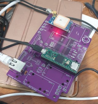
Ahh, thanks for that - I wasn't aware that there were limited working permutations and the pin was dictated by the hardware design. As it happens I just soldered a wire from PPS to Pin38 on the Teensy socket and cut the trace that goes to pin35... Works fine now obviously but a little messy.

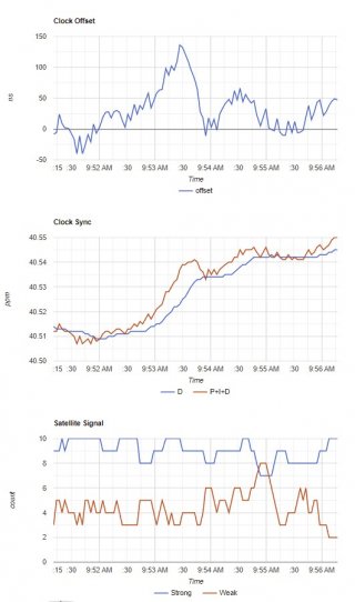
I am also getting a clock sync of 40.2 - 40.6ppm which seems to be way off what others are getting... The room is about 22C and the board is open-air. My GPS is a (presumably) knockoff M8N.

Is this indicative of an issue? Or just a crystal at the limit of spec?

teensyclock.jpg

20211215_095855 (Medium).jpg

Regards
 
Thanks for the pointer, the other 2 don't appear to be broken out on the T4.1 (GPIO_AD_B0_14 and GPIO_AD_B0_10)...

I'll not bash my head against that brick wall any longer and embrace pin35 with a selectable trace on my next board spin :)

Cheers - N
 
Back
Top