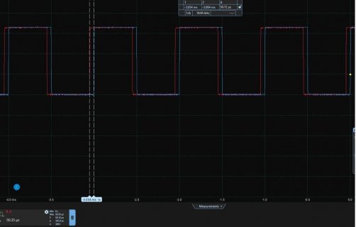
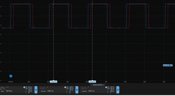
The pulse train is quite stable but there appears to be a lot of fluctuations in readings. I am measuring a period of about 1001 us on Pin A and Pin B and edgePinA->edgePinB around 69.79 us with an oscilloscpe-See screenshot attached
10:46:30.594 -> PinA=1 PinB=1 PeriodPinA=959.789 us PeriodPinB=860.120 us, edgePinA->edgePinB in 136.595 us, edgePinB->edgePinA in 831.372 us
10:46:30.909 -> PinA=1 PinB=1 PeriodPinA=842.486 us PeriodPinB=990.729 us, edgePinA->edgePinB in 74.672 us, edgePinB->edgePinA in 852.206 us
10:46:31.179 -> PinA=1 PinB=0 PeriodPinA=900.215 us PeriodPinB=949.079 us, edgePinA->edgePinB in 94.427 us, edgePinB->edgePinA in 861.200 us
10:46:31.494 -> PinA=0 PinB=0 PeriodPinA=897.334 us PeriodPinB=949.554 us, edgePinA->edgePinB in 120.552 us, edgePinB->edgePinA in 881.348 us
10:46:31.794 -> PinA=0 PinB=0 PeriodPinA=992.260 us PeriodPinB=921.175 us, edgePinA->edgePinB in 107.647 us, edgePinB->edgePinA in 882.617 us
10:46:32.093 -> PinA=0 PinB=1 PeriodPinA=905.304 us PeriodPinB=869.002 us, edgePinA->edgePinB in 132.384 us, edgePinB->edgePinA in 795.635 us
10:46:32.393 -> PinA=1 PinB=1 PeriodPinA=993.481 us PeriodPinB=945.772 us, edgePinA->edgePinB in 95.978 us, edgePinB->edgePinA in 898.303 us
10:46:32.694 -> PinA=1 PinB=1 PeriodPinA=966.192 us PeriodPinB=944.498 us, edgePinA->edgePinB in 96.594 us, edgePinB->edgePinA in 884.823 us
10:46:33.009 -> PinA=0 PinB=0 PeriodPinA=902.933 us PeriodPinB=923.065 us, edgePinA->edgePinB in 106.763 us, edgePinB->edgePinA in 847.659 us
10:46:33.279 -> PinA=0 PinB=0 PeriodPinA=889.189 us PeriodPinB=915.680 us, edgePinA->edgePinB in 110.240 us, edgePinB->edgePinA in 835.892 us
10:46:33.608 -> PinA=0 PinB=0 PeriodPinA=871.553 us PeriodPinB=949.793 us, edgePinA->edgePinB in 94.095 us, edgePinB->edgePinA in 845.558 us
10:46:33.899 -> PinA=1 PinB=1 PeriodPinA=897.630 us PeriodPinB=961.287 us, edgePinA->edgePinB in 88.631 us, edgePinB->edgePinA in 863.356 us
Well, here in Holland, the same code on a T41 shows this:
PinA=0 PinB=1 PeriodPinA=2000.000 us PeriodPinB=1001.362 us, edgePinA->edgePinB in 1441.571 us, edgePinB->edgePinA in 45.741 us
PinA=0 PinB=1 PeriodPinA=2000.000 us PeriodPinB=1001.366 us, edgePinA->edgePinB in 903.056 us, edgePinB->edgePinA in 638.283 us
PinA=0 PinB=0 PeriodPinA=2000.000 us PeriodPinB=1001.360 us, edgePinA->edgePinB in 1258.351 us, edgePinB->edgePinA in 228.946 us
PinA=0 PinB=1 PeriodPinA=2000.000 us PeriodPinB=1001.360 us, edgePinA->edgePinB in 719.325 us, edgePinB->edgePinA in 821.579 us
PinA=0 PinB=0 PeriodPinA=2000.000 us PeriodPinB=1001.358 us, edgePinA->edgePinB in 1073.213 us, edgePinB->edgePinA in 414.070 us
PinA=0 PinB=1 PeriodPinA=2000.000 us PeriodPinB=1001.360 us, edgePinA->edgePinB in 750.261 us, edgePinB->edgePinA in 528.799 us
PinA=0 PinB=1 PeriodPinA=2000.000 us PeriodPinB=1001.361 us, edgePinA->edgePinB in 940.864 us, edgePinB->edgePinA in 600.401 us
PinA=0 PinB=0 PeriodPinA=2000.000 us PeriodPinB=1001.356 us, edgePinA->edgePinB in 1294.330 us, edgePinB->edgePinA in 192.924 us
PinA=0 PinB=1 PeriodPinA=2000.000 us PeriodPinB=1001.356 us, edgePinA->edgePinB in 753.985 us, edgePinB->edgePinA in 787.142 us
PinA=0 PinB=0 PeriodPinA=2000.000 us PeriodPinB=1001.355 us, edgePinA->edgePinB in 1106.703 us, edgePinB->edgePinA in 380.541 us
PinA=0 PinB=1 PeriodPinA=2000.000 us PeriodPinB=1001.355 us, edgePinA->edgePinB in 583.187 us, edgePinB->edgePinA in 840.037 us
PinA=0 PinB=1 PeriodPinA=2000.000 us PeriodPinB=1001.359 us, edgePinA->edgePinB in 973.028 us, edgePinB->edgePinA in 568.215 us
PinA=0 PinB=0 PeriodPinA=2000.000 us PeriodPinB=1001.358 us, edgePinA->edgePinB in 1326.297 us, edgePinB->edgePinA in 160.970 us
PinA=0 PinB=1 PeriodPinA=2000.000 us PeriodPinB=1001.360 us, edgePinA->edgePinB in 786.156 us, edgePinB->edgePinA in 755.052 us
PinA=0 PinB=0 PeriodPinA=2000.000 us PeriodPinB=1001.356 us, edgePinA->edgePinB in 1138.863 us, edgePinB->edgePinA in 348.378 us
PinA=0 PinB=0 PeriodPinA=2000.000 us PeriodPinB=1001.358 us, edgePinA->edgePinB in 599.446 us, edgePinB->edgePinA in 904.961 us
PinA=0 PinB=1 PeriodPinA=2000.000 us PeriodPinB=1001.357 us, edgePinA->edgePinB in 1004.913 us, edgePinB->edgePinA in 536.321 us
PinA=0 PinB=0 PeriodPinA=2000.000 us PeriodPinB=1001.353 us, edgePinA->edgePinB in 1357.195 us, edgePinB->edgePinA in 130.025 us
PinA is on pin 13 which has a 500 Hz square wave that is made by the same code, using Teensy Arduino timers with 1 ms, toggling 'LED', so blinking at 500 Hz (added that for testing). PinB is on a 1 kHz pulse generator, manually tuned to 1 kHz, so showing 1000 +/-2 us is good.
I'd argue it is dead stable, Maybe your pulses are not?
A good scope would allow "Envelope" and "Persistence to infinity". Does your scope then still suggest your signals are super stable? Or a ground wire is missing? Or the pulses go > 3.3V when high?