Trouble getting rotary encoder to work with Teensy 4.0

I've used rotary encoders with several projects in the past with both Arduino Uno and MEGA. I'm using a 200 pulse/rotation NPN incremental encoder. For this project I need to use 4x encoders, so porting over to the Teensy 4.0 because I'll need 8 total interrupt pins.

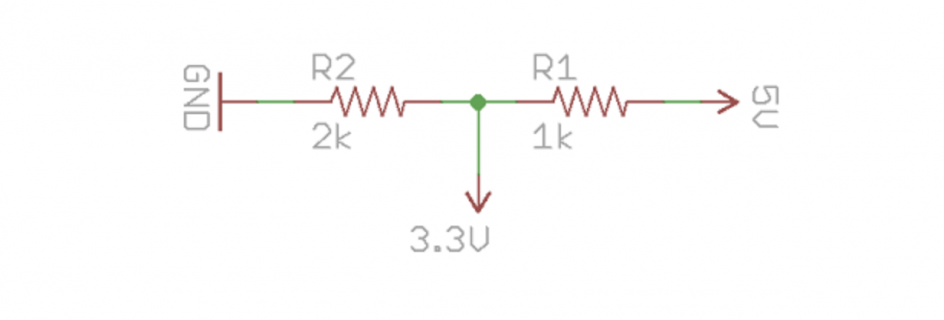
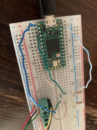
However, when I stripped down my basic working encoder code to test with Teensy 4.0, I'm not registering any changed when I spin. The one issue I may be having is the addition of two simple separate voltage dividers at each of the encoder digital pins to bring the 5V signal down to 3.3V for the Teensy inputs (using a basic 2k/1k divider). Image attached for reference. Ultimately, I'm planning to use a TXS0108E level conversion module, thinking this will help the speed. But I thought I could at least prove out my prototype with a simple voltage divider. Could this be why I'm not registering any changes when I spin the encoder?

Again, I'm A/B testing here with an UNO, and the circuit/code works with the UNO (without the voltage divider), but when I wire the encoder output through the voltage divders, I can't get the Teensy to register any change with the encoder.

Any help would be appreciated!

Code:
int encoderPin1 = 2;
int encoderPin2 = 3;
volatile int lastEncoded = 0;
volatile long encoderValue = 10000;
int lastMSB = 0;
int lastLSB = 0;

void setup() {
  Serial.begin (9600);
  Serial.println("hello");
  pinMode(encoderPin1, INPUT);
  pinMode(encoderPin2, INPUT);
  digitalWrite(encoderPin1, HIGH);
  digitalWrite(encoderPin2, HIGH);
  attachInterrupt(digitalPinToInterrupt(2), updateEncoder, CHANGE);
  attachInterrupt(digitalPinToInterrupt(3), updateEncoder, CHANGE);
}

void loop(){
  Serial.println(encoderValue);     
}

void updateEncoder(){
  int MSB = digitalRead(encoderPin1);
  int LSB = digitalRead(encoderPin2);
  int encoded = (MSB << 1) |LSB;
  int sum  = (lastEncoded << 2) | encoded;
  if(sum == 0b1101 || sum == 0b0100 || sum == 0b0010 || sum == 0b1011) encoderValue++;
  if(sum == 0b1110 || sum == 0b0111 || sum == 0b0001 || sum == 0b1000) encoderValue--;
  lastEncoded = encoded;
}
 

Attachments

  • Screenshot 2024-10-05 at 10.12.14 PM.png
    Screenshot 2024-10-05 at 10.12.14 PM.png
    53.3 KB · Views: 31
  • IMG_2692b.jpg
    IMG_2692b.jpg
    186.6 KB · Views: 30
Code:
  pinMode(encoderPin1, INPUT);
  pinMode(encoderPin2, INPUT);
  digitalWrite(encoderPin1, HIGH);
  digitalWrite(encoderPin2, HIGH);
These lines look a bit strange.
Are the encoder outputs open-drain and the microcontroller's inputs intended to have active pullups? If so the pinMode calls should be using INPUT_PULLUP, and you can safely connect them without the voltage divider resistors.

(This would explain why you're not reading anything - the voltage divider resistors are much lower than the Teensy's pullup values, so they're effectively grounding the inputs.)
 
Last edited:
I've used rotary encoders with several projects in the past with both Arduino Uno and MEGA. I'm using a 200 pulse/rotation NPN incremental encoder. For this project I need to use 4x encoders, so porting over to the Teensy 4.0 because I'll need 8 total interrupt pins.

However, when I stripped down my basic working encoder code to test with Teensy 4.0, I'm not registering any changed when I spin. The one issue I may be having is the addition of two simple separate voltage dividers at each of the encoder digital pins to bring the 5V signal down to 3.3V for the Teensy inputs (using a basic 2k/1k divider). Image attached for reference. Ultimately, I'm planning to use a TXS0108E level conversion module, thinking this will help the speed. But I thought I could at least prove out my prototype with a simple voltage divider. Could this be why I'm not registering any changes when I spin the encoder?
If the encoder is powered from 5V and open-collector, you only need a single pull-up to the Teensy 3.3V supply.

It it's output is push-pull you will need a divider from the encoder output to the Teensy - I can't tell from your diagram where things are connected - can you clarify this?

Also if you know what encoder you are using, please tell us, we are groping in the dark otherwise.
 
Not sure what encoders you are using and if these need something different, but have you tried the encoder library which comes with the teensy? There are also example sketches for it.
 
Also if you know what encoder you are using, please tell us, we are groping in the dark otherwise.
Yes, there are so many rotary encoders out there that knowing which one is mandatory.
You may want to have a look at this thread and this thread for using rotary encoders with NPN output stage.

Paul
 
Hello all, thanks so much to everyone for their responses. I am an artist, and will often get a kludgey thing working, and then use it over and over and never look back. Yes, I didn't know about the "input_pullup", I had been under the impression from projects past that writing the digital pin to "HIGH" did a similar thing as engaging the internal pull-up resistor. I've updated my working code to use this (as well as the encoder library...). Also, having always used UNO's and MEGA's I clearly didn't understand how to level shift...! So @jmarsh was right, I was simply grounding the data lines.

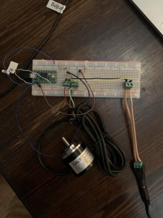
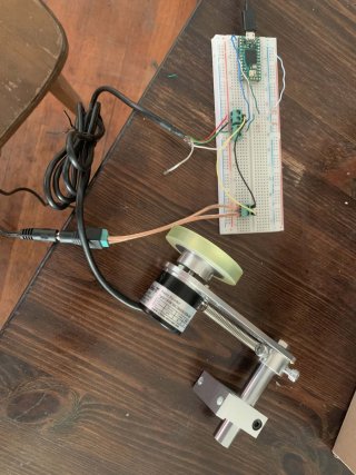
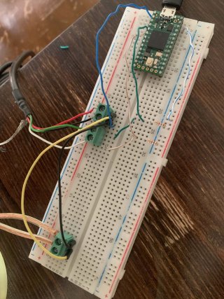
I have everything working now on the Teensy 4.0, incorporating everyone's feedback. I'm using 1K resistors between Teensy's 3.3V source and the 2x data lines coming out of encoder before connecting to pins 2 and 3. I'm including some images and my working code for other seekers, included at the end of this post. I do have a couple of question remaining, if anyone feels inclined to humor me...

Question #1: What's happening with the voltage in the rotary encoder?
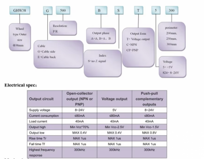
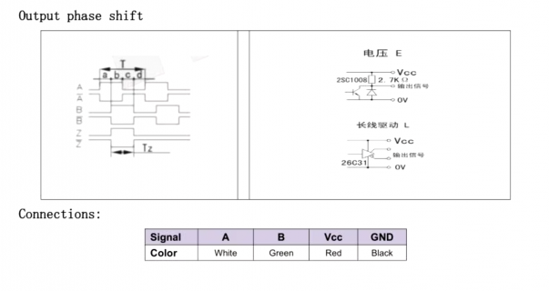
So the rotary encoder model is GHW38G200BSC824-200. It's a cheap one I bought several years ago online. I don't have the data sheet, but took some screenshots from the online seller's listing. It is an NPN open collector type, and needs 8-24V for power. The "data sheet" states the output High is "Min Vcc * 70%", which I took to mean 8v*.7 or ~5.6v. However when I connect the encoder to 12V DC (completely disconnected from the Teensy circuit) and meter the outputs, the maximum voltage I read on either output is 0.53v. I've also tested with a 9v supply, and the highest reading is 0.48v. So slightly lower, but perhaps negligible? Can anyone shed light on what's happening here? Since everything works as expected when I connect everything to the Teensy using the pull-up resister between these encoder outputs and Teensy's 3.3v, I'm assuming this is intentional. I just feel like I'm missing one conceptual piece of the puzzle...

Question #2: Would anyone suggest additional components?
I'm using the Teensy 4.0 to read 4x of these rotary encoders along with 4x IR photoresistors. Each encoder will have around 10' of AWG24 CAT5e cable between the encoder and the Teensy 4.0. Would anyone recommend considering additional components at either end of the cable run for stability?

Thanks again for everyone's help!
-Joshua

Code:
#include <Encoder.h>

volatile long oldPos[4] = { 0, 0, 0, 0 };
volatile long newPos[4] = { 0, 0, 0, 0 };
int IR_sensorPins[4] = { A0, A1, A2, A3 };
int IR_vals[4] = { 0, 0, 0, 0 };

Encoder Enc0(2, 3);
Encoder Enc1(4, 5);
Encoder Enc2(6, 7);
Encoder Enc3(8, 9);

void setup() {
  Serial.begin(115200);  //Matches Baud in Max App
  Serial.println("ShakeHandsWithMaxMSP");
}

void loop() {
  newPos[0] = Enc0.read();
  newPos[1] = Enc1.read();
  newPos[2] = Enc2.read();
  newPos[3] = Enc3.read();
  for (int i = 0; i < 4; i++) {
    if (newPos[i] != oldPos[i]) {
      oldPos[i] = newPos[i];
      IR_vals[i] = analogRead(IR_sensorPins[i]);
      Serial.print(i);
      Serial.print(" ");
      Serial.print(newPos[i]);
      Serial.print(" ");
      Serial.println(IR_vals[i]);
    }
  }
  delay(10);
}
 

Attachments

  • IMG_2699.jpg
    IMG_2699.jpg
    228.5 KB · Views: 27
  • IMG_2700.jpg
    IMG_2700.jpg
    240.5 KB · Views: 24
  • IMG_2701.jpg
    IMG_2701.jpg
    189 KB · Views: 29
  • CALT_GHW38_pg1.png
    CALT_GHW38_pg1.png
    1.2 MB · Views: 28
  • CALT_GHW38_pg2.png
    CALT_GHW38_pg2.png
    223.9 KB · Views: 21
Question #1: What's happening with the voltage in the rotary encoder?
So the rotary encoder model is GHW38G200BSC824-200. It's a cheap one I bought several years ago online. I don't have the data sheet, but took some screenshots from the online seller's listing. It is an NPN open collector type, and needs 8-24V for power. The "data sheet" states the output High is "Min Vcc * 70%", which I took to mean 8v*.7 or ~5.6v. However when I connect the encoder to 12V DC (completely disconnected from the Teensy circuit) and meter the outputs, the maximum voltage I read on either output is 0.53v. I've also tested with a 9v supply, and the highest reading is 0.48v. So slightly lower, but perhaps negligible? Can anyone shed light on what's happening here? Since everything works as expected when I connect everything to the Teensy using the pull-up resister between these encoder outputs and Teensy's 3.3v, I'm assuming this is intentional. I just feel like I'm missing one conceptual piece of the puzzle...
Open collector means it never drives the outputs high, only low. When the encoder wants to output a "high" it just leaves the output open, disconnected from anything - so what you're measuring with the meter at that time is just a floating line. This has the advantage that the encoder can be used with any voltage IO by using pull-ups.
You don't actually need the physical pull-up resistors; if the Teensy's pins are configured for INPUT_PULLUP mode they will use internal pullups instead.

Yes, I didn't know about the "input_pullup", I had been under the impression from projects past that writing the digital pin to "HIGH" did a similar thing as engaging the internal pull-up resistor.
It does do that. I just meant it looked "weird" because the pins were being configured to use internal pull-ups while being connected to an active voltage divider.
 
Back
Top