U2 and D4 hot, 3.3v shorted to GND

UnhappyWithoutU

Active member
Hey everyone!

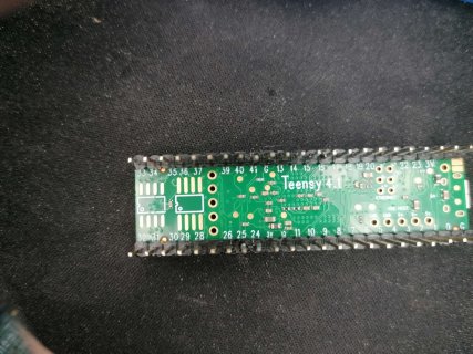
Just chosed a random of my many teensy board, but It didnt turned on at all.
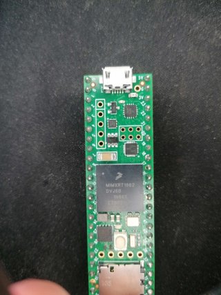
Then I realized that U2 is getting very(!) hot. Also Q1 is extremely hot.

1714593921560.png


After that I hooked up my multimeter to check if any pins are shorted, sadly I realized yes.
3.3V is shorted to Ground.

Does anyone have an idea how to fix this problem?
Soldering SMD is not a problem for me!
Greetings from germany
 
Last edited:
Find the short? Do you have a thermal camera, sometimes a short in a PCB shows up as a hot spot.
 
Nah I dont have a infrared camera. Also im not very sure how to find where the short comes from. Unsoldering parts and checking if they are in good condition?
 
So there's 15 ohms from GND to 3V3. Regarding to the schematics there are 13 smd capacitors and 1 resistor in between those two pins, also U2, U3, U4 and U6. How would I start finding the broken one? De/resoldering each after another?

Edit: seems like R7 is not connected between 3v3 and GND, my fault
 
Try measuring the 3.3V voltage while the power is on the input parts are hot. Do not rely on ohms measurement.

If the voltage is very low, only several mV, that's a sure sign the short is metal. Usually these problems can be fixed if you find and remove the metal.

If the voltage is higher, like 0.3V to 0.9V, that probably means the short is a semiconductor. This sort of problem is rarely fixable.
 
It seems like the full 3.3volts are there. Input voltage is 4.7volts. I guess because of the hot parts which draw a big amount of current due to the 15 ohms between 3.3 and 0v. Thats weird
Any other idea?
 
Last edited:
This is quite weird indeed.

Is this Teensy actually working, like you can load new programs and they run correctly?
 
No, the pc doesnt even detect the board, also I have a fairly fresh windows install, my laptop also doesnt recognize it. Other teensy 4.1 or 4.0 do work. Also no LED lids up when trying to press the boot button
 
On Teensy or pretty much any circuit board, if you have a large current flowing an unknown path, one thing you can do is measure voltage drop along the power and ground. You'll need a multimeter with sensitive mV scale. Then just touch any 2 GND points. If you get 0, you can conclude little or no current is flowing between those 2 points. But if you get several mV, that implies a substantial current. Repeat all over the PCB to get an idea of where the current is really flowing.
 
Last edited:
This is a really strange case. Normally when a board goes badly and consumes too much current for things to get really hot, either the 5V power or the 3.3V power measures low. But you said you measured 4.7V and 3.3V. Normally when a large current flows, at least a few mV drops along the PCB. But you measured 0.0mV.

You also said the red LED doesn't respond in any way when you press the pushbutton. That too doesn't make much sense. If the U2 chip has 3.3V power, it really should respond somehow.

I really wish I had an idea for you, but so far everything you've reported sounds so far from anything I can understand.

Maybe if you get someone to assist with a camera (even most cell phones can do this if you have a bright light) to get photos of the way you're actually measuring and hopefully good close ups of the hardware, perhaps something in the pictures will stir up some ideas? Just try to imagine everyone reading this thread. It's words only that just don't add up to any understandable scenario. Photos often work wonders on this forum, especially when the problem has some sort of misunderstanding where words always say the correct thing but a photo lets us see what really happened. If you do shoot photos, please try to have someone else work the camera (phone?) while you made the measurements and small details like where the wires touched so we can see how you measured and what was really appearing on the multimeter. But even that seems like a long-shot at this point.
 
Yeah, thats the problem im at right now.

I have used this board as a Joystick(keyboard) at some time and it worked all time long fine.
Just grabbed it again and wanted to use it. No reaction.

I a bit experienced in this electronic stuff and understand what you mean. It atleast should respond in any type.
I will make some images or videos of it and send them in here, maybe they could help somehow.

I already repaired another teensy I ripped of some SMD condensators at some time and its still working like a charm, was hoping to get this working here too again.

Greetings
 
I attached some images of my teensy 4.1
I also cleaned the board with some chemical pcb cleaner to make sure no dirt shorts somewhere.

I measured again and still have a voltage drop of 0.0mV over all GND pins together and/or the 3.3v pins together.
Measuring from 3.3v to GND results in 0.0mV. And also I saw 16-19.5Ω from 3.3v to GND regarding on how hot the pcb is when turned OFF! When turned ON it drops to 0Ω.

Yes I know some header pins are not soldered on properly
 

Attachments

  • IMG_20240504_133331.jpg
    IMG_20240504_133331.jpg
    383.4 KB · Views: 8
  • IMG_20240504_133326.jpg
    IMG_20240504_133326.jpg
    470 KB · Views: 8
  • IMG_20240504_133344.jpg
    IMG_20240504_133344.jpg
    187.7 KB · Views: 8
  • IMG_20240504_133350.jpg
    IMG_20240504_133350.jpg
    163.2 KB · Views: 9
Uh im really unsure why I wrote that. Im Sorry.

Here again bulleted to make it clear:
  • 3.3V is shorted to GND (diode tester beeps)
  • 3.3V to GND is at 16-19.5Ω when turned OFF (varying because of heat after it was on)
  • 3.3V to GND is at 0Ω when turned ON (always)
  • I tried many combinations for the 3 GND pins, resulting in the same every time.

Measuring Voltage Drop when ON, between:
  • 3.3V and 3.3V results in 0.0mV - 0.1mV
  • GND and GND results in 0.0mV
 
3.3V to GND is at 0Ω when turned ON (always)

You can't measure resistance when the circuit is powered up. Measure the _voltage_ when a circuit is powered.
19 ohms is not a hard short, suggests a failed semiconductor, not a metal-to-metal short circuit.
 
Hey Unhappyman, are you still unhappyWithoutU4?
That U4 would be the first one I would unsolder to see if the 3v3 short disappears.
 
Wouldnt it make sense that it's the bootloader Chip itself? Since it's not booting at All even when the 3.3v still exist

Probably not, but maybe...

The bootloader chip is not involved in the software startup process. It does not function the same way as a traditional software-only bootloader, which runs first and then jumps to your program. When Teensy starts up, the bootloader does NOT run any code on the main RT1062 chip. Software startup doesn't depend on U2.

However, the bootloader chip does participate in the hardware power supply startup process. It is described in the "Power Up Sequence" on this page (scroll down if needed)


Look for step #7 for the U2 chip's role. That page has little Javascript buttons that highlight each of the power supply startup steps on the schematic. Hopefully that help you to understand the U2 chip's role in power supply startp.

You can measure the VDD_SOC_IN test point to confirm whether the DCDC hardware turned on.

test_points_teensy41.png
 
Back
Top