luni
Well-known member
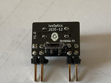
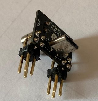
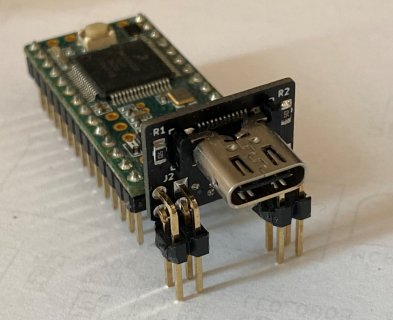
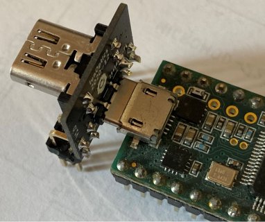
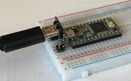
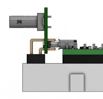
Inspired by vjmuzik's thread https://forum.pjrc.com/threads/65633-T4-1-External-USB-C-Connector and my quest to get familiar with KiCad I thought it might be fun to do a simple USB-C adapter board. The CC configuration (two 5k1 pulldowns) will signal the host to provide 5V, up to 3A on VBUS.
If necessary, the actual power provided by a host (0.5A/2.5W, 1.5A/7.5W or 3A/15W) can be found out by measuring the voltage on CC1/CC2. Here a corresponding Microchip App note http://ww1.microchip.com/downloads/en/appnotes/00001953a.pdf. The CC signals and GND/5V are available on the pin headers which will also provide mechanical stability.
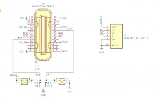

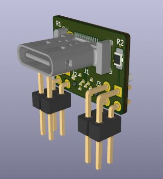
I wonder if this setup will also work for the higher usb frequency on the T4 boards. Here the relevant DP/DN traces:

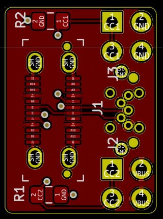
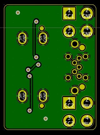
Bottom fill -> GND, Top fill -> VBUS
Anything to improve? Comments?
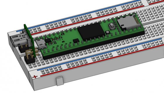
EDIT: here the link to the Onshape 3d design if someone is interested: https://cad.onshape.com/documents/4...e88da873fdf43474fa/e/86c68fc449c82f47aacdc46e
If necessary, the actual power provided by a host (0.5A/2.5W, 1.5A/7.5W or 3A/15W) can be found out by measuring the voltage on CC1/CC2. Here a corresponding Microchip App note http://ww1.microchip.com/downloads/en/appnotes/00001953a.pdf. The CC signals and GND/5V are available on the pin headers which will also provide mechanical stability.


I wonder if this setup will also work for the higher usb frequency on the T4 boards. Here the relevant DP/DN traces:


Bottom fill -> GND, Top fill -> VBUS
Anything to improve? Comments?
EDIT: here the link to the Onshape 3d design if someone is interested: https://cad.onshape.com/documents/4...e88da873fdf43474fa/e/86c68fc449c82f47aacdc46e
Last edited:


