TelephoneBill
Well-known member
A cheap GPS module, with an electrical output signal that you can precisely control, is a very useful bit of equipment for Teensy testing or experimentation. The "UBlox NEO M8N module" is just such a piece of kit and is widely available at very low prices on eBay. The aim of this 'primer' is to share some experience on using this module with other Teensy users who may not be familiar with it.
This GPS module is normally sold with its own small antenna, and when placed near a window with a clear sky view, will phase lock with both GPS and/or GLONASS satellites (even at the same time). When phase lock with four or more satellites is achieved, it can provide an electrical output signal that is precisely synchronised to Universal Co-ordinated Time (UTC). This output may be in the form of pulses having a user specified delay (w.r.t UTC) accurate to nanoSeconds, or the output can be specified as a frequency from 1 Hz to 10 MHz.
The module that you purchase needs a little skill with a soldering iron first to make an electrical output signal available, and you will also need to purchase a "USB to Low Level TTL" cable if you want to use the free UBlox "U-center" software to drive it from a PC. These USB cables require a driver download to function, and there are a few surprises in store - as a USB device - for the unwary. But I hope to guide users through these "surprises" so that they can get up and running as quickly as possible.
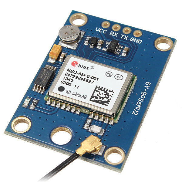
The following two pictures illustrate how the module needs to be modified in order to make the output signal available. These modules were never designed to have an output available, only to blink an on-board LED. But the UBlox component (via Pin 3) has this ability to control this pin signal via software, so by soldering a wired connection in parallel with the "102" resistor (that drives the LED), then you can make the pulses/frequencies available, as well as the LED. I normally solder two short wires to the module first (Orange = signal, Black = GND), and then use clip wires to connect to other devices. The output level is 3v3 so should be compatible with Teensy inputs - BUT MAKE SURE WITH A SCOPE FIRST BEFORE YOU CONNECT. I take NO RESPONSIBILITY if you damage your Teensy or other equipment !!! The responsibility for safe operation is YOURS to own ALONE. Ground returns and power supplies can throw up some unexpected situations.


The "surprises" with "USB to Low Level TTL converter" cables are a result of poor manufacturing. For Windows type PCs, you may plug the USB connector into a spare computer socket and then discover that your display screen goes "crazy" with "phantom mouse click" syndrome. Suddenly, the screen looks as if random "mouse-click" events are happening all over the place. And they won't stop happening until you remove the USB connector (which you should do).
I confess to never having found a solution that works in all cases. The cause of this effect is the fact that the PC thinks your device is an alternative mouse type device - even though it isn't. That is because the driver for the chip inside the cable is not correctly configured. Some "phoney chips" have been produced to emulate genuine types, and the manufacturer may have changed the driver to try protect their business from being ripped off. Search the web if this happens to you as the problem is well known - and solutions do work - a common one is to download an earlier driver. Another issue that is involved is invalid VendorIDs or ProductIDs. The VID/PID combination is supposed to make USB devices unique and to allow the operating system to make the correct choice for a driver.
I AM SORRY THAT I CANNOT SUPPLY DRIVER SOFTWARE, SO DON'T ASK ME - you will need to search the web for sources for your particular USB device. Again, this is your choice/responsibility.
You may also want to check the "Device Manager" facility with WIN type PCs. Make sure that your device IS recognised under the USB "Ports (COM & LPT)" option, and make sure it is NOT recognised as "Mice and other pointing devices" (if it is then be careful to uninstall YOUR USB entry, and not that of your normal mouse - if you get this wrong, you could end up with losing mouse control completely). Again, this is YOUR RESPONSIBILITY to manage and not mine.
If I get "phantom mouse" syndrome, I normally try unplugging - waiting a few seconds - then try plugging in again. It seems to be that one out of several attempts will be successful. Once it is successful, then it usually stays quiet until you disturb it. If you power down your PC, make sure that you leave the USB cable connected until shutdown is complete. Make sure the cable is also connected before you power up again next time - this is trying to maintain the same "configuration" that was working before. Also never power down with the "software" STILL CONNECTED to the device - you make this "connect" choice inside the U-Center software itself. AND NEVER, EVER, EVER change the USB device during the power up or power down phase (when in progress) - that can be catastrophic for the operating system.
The problems associated with these USB converter cables is a real pain. But once you have it operational with the NEO M8N module, then the effort will be justly rewarded in the rich features that the module can provide.
When you have the USB cable and the NEO M8N module plugged in and operationally working with your PC (stable and recognised in Device Manager), you are then ready to download the U-Center software and install it. You can find the download available here... https://www.u-blox.com/en/product/u-center-windows.
With the U-Center software running, you need to select the RECEIVER PORT setting from the main menu. Below is an example picture.

Here I have chosen the (menu option) VIEW - SKY VIEW window for the main area. Over on the far right you see the signal level sub-windows. When you first start up the software, if the module has been correctly recognised, then you will see some "Blue" signal indicators popping up. These remain "Blue" until the software/module has correctly identified at least four satellite signals. This can take quite some time from a "Cold Start". On the module itself, there is a steady power indicator LED to show that USB power is being used. Once four satellites have been "locked", then the module will start to blink its GREEN LED at a rate of one blink per second. This rate is configurable, as we shall see shortly. Also, when four satellites have been locked, the signal indicators for those satellites will change color to "Green". That signal will also now be available as an electrical output on your soldered ORANGE/BLACK wires. Check this with a scope.
To change the signal output on your newly soldered wires, select VIEW-CONFIGURATION VIEW from the main menu. Expand this window to its full size. Scroll down (if needs be) and click the option "TP5 (Timepulse 5). The three most useful features of this TP5 facility for pulses are "Period Locked", "Length Locked" and "User Delay". Make your selection - as you desire - and then click on the SEND button in the bottom left-hand corner. Your selection will not alter the module until this SEND button is activated. Once sent, then the module will remember the commands you have sent it - even if you then disconnect the software completely.
The "locked" selections can occasionally be interrupted, if the module loses its four satellites minimum signal requirement. At that point, you will see the signal indicators go all "Blue" and remain that way until lock is re-established. They normally come back again, but this all depends on the quality of the signals that your MODULE ANTENNA is receiving. Also, when you lose the lock condition, the output pulse to your soldered wires will also be interrupted - as will the blink of the GREEN LED.
The U-Center software has far too many options for me to be able to describe in this primer. I leave most of these for users to explore and experiment with.
One last word of advice... the signals that you extract via your soldered wires are "fragile" in respect of the signal propagation down the wiring to whatever device you hook them up to. The "transmit" output of the M8N module expects to see "correct propagation impedance termination" applied to your output. This is not normally an issue below 1 MHz output conditions. But when you start to move upwards towards 10 MHz, then this becomes more and more important. If the output termination is not sufficiently within the "spec", then you will get reflections back down the wiring - and this may shut down the module when it attempts to "protect itself" from your handiwork. This manifests itself in an odd way, and produces a cycling of "lock" followed by "unlock" and then back to "lock again". This will keep happening all the time that the module objects to your wiring conditions. It doesn't seem to cause any damage to the module (providing there are no short circuits) and will recover if the frequency is changed to something less than 1 MHz - or if you disconnect your wiring or loading. Only experiment will show you what you can and cannot get away with in respect of impedance termination.
I hope this primer has been of service to beginners who would like a GPS controlled signal generator. I cannot promise to answer all queries arising either - especially as I'm a WIN PC user not a LINUX user. Maybe others can handle these type of questions.
Have fun and enjoy your UBlox NEO M8N module - despite the pains given by the USB conversion cables ! If I'm slow to answer any queries, it will probably be because I'm away from my office for some reason. I don't use mobile devices.
This GPS module is normally sold with its own small antenna, and when placed near a window with a clear sky view, will phase lock with both GPS and/or GLONASS satellites (even at the same time). When phase lock with four or more satellites is achieved, it can provide an electrical output signal that is precisely synchronised to Universal Co-ordinated Time (UTC). This output may be in the form of pulses having a user specified delay (w.r.t UTC) accurate to nanoSeconds, or the output can be specified as a frequency from 1 Hz to 10 MHz.
The module that you purchase needs a little skill with a soldering iron first to make an electrical output signal available, and you will also need to purchase a "USB to Low Level TTL" cable if you want to use the free UBlox "U-center" software to drive it from a PC. These USB cables require a driver download to function, and there are a few surprises in store - as a USB device - for the unwary. But I hope to guide users through these "surprises" so that they can get up and running as quickly as possible.
The following two pictures illustrate how the module needs to be modified in order to make the output signal available. These modules were never designed to have an output available, only to blink an on-board LED. But the UBlox component (via Pin 3) has this ability to control this pin signal via software, so by soldering a wired connection in parallel with the "102" resistor (that drives the LED), then you can make the pulses/frequencies available, as well as the LED. I normally solder two short wires to the module first (Orange = signal, Black = GND), and then use clip wires to connect to other devices. The output level is 3v3 so should be compatible with Teensy inputs - BUT MAKE SURE WITH A SCOPE FIRST BEFORE YOU CONNECT. I take NO RESPONSIBILITY if you damage your Teensy or other equipment !!! The responsibility for safe operation is YOURS to own ALONE. Ground returns and power supplies can throw up some unexpected situations.
The "surprises" with "USB to Low Level TTL converter" cables are a result of poor manufacturing. For Windows type PCs, you may plug the USB connector into a spare computer socket and then discover that your display screen goes "crazy" with "phantom mouse click" syndrome. Suddenly, the screen looks as if random "mouse-click" events are happening all over the place. And they won't stop happening until you remove the USB connector (which you should do).
I confess to never having found a solution that works in all cases. The cause of this effect is the fact that the PC thinks your device is an alternative mouse type device - even though it isn't. That is because the driver for the chip inside the cable is not correctly configured. Some "phoney chips" have been produced to emulate genuine types, and the manufacturer may have changed the driver to try protect their business from being ripped off. Search the web if this happens to you as the problem is well known - and solutions do work - a common one is to download an earlier driver. Another issue that is involved is invalid VendorIDs or ProductIDs. The VID/PID combination is supposed to make USB devices unique and to allow the operating system to make the correct choice for a driver.
I AM SORRY THAT I CANNOT SUPPLY DRIVER SOFTWARE, SO DON'T ASK ME - you will need to search the web for sources for your particular USB device. Again, this is your choice/responsibility.
You may also want to check the "Device Manager" facility with WIN type PCs. Make sure that your device IS recognised under the USB "Ports (COM & LPT)" option, and make sure it is NOT recognised as "Mice and other pointing devices" (if it is then be careful to uninstall YOUR USB entry, and not that of your normal mouse - if you get this wrong, you could end up with losing mouse control completely). Again, this is YOUR RESPONSIBILITY to manage and not mine.
If I get "phantom mouse" syndrome, I normally try unplugging - waiting a few seconds - then try plugging in again. It seems to be that one out of several attempts will be successful. Once it is successful, then it usually stays quiet until you disturb it. If you power down your PC, make sure that you leave the USB cable connected until shutdown is complete. Make sure the cable is also connected before you power up again next time - this is trying to maintain the same "configuration" that was working before. Also never power down with the "software" STILL CONNECTED to the device - you make this "connect" choice inside the U-Center software itself. AND NEVER, EVER, EVER change the USB device during the power up or power down phase (when in progress) - that can be catastrophic for the operating system.
The problems associated with these USB converter cables is a real pain. But once you have it operational with the NEO M8N module, then the effort will be justly rewarded in the rich features that the module can provide.
When you have the USB cable and the NEO M8N module plugged in and operationally working with your PC (stable and recognised in Device Manager), you are then ready to download the U-Center software and install it. You can find the download available here... https://www.u-blox.com/en/product/u-center-windows.
With the U-Center software running, you need to select the RECEIVER PORT setting from the main menu. Below is an example picture.
Here I have chosen the (menu option) VIEW - SKY VIEW window for the main area. Over on the far right you see the signal level sub-windows. When you first start up the software, if the module has been correctly recognised, then you will see some "Blue" signal indicators popping up. These remain "Blue" until the software/module has correctly identified at least four satellite signals. This can take quite some time from a "Cold Start". On the module itself, there is a steady power indicator LED to show that USB power is being used. Once four satellites have been "locked", then the module will start to blink its GREEN LED at a rate of one blink per second. This rate is configurable, as we shall see shortly. Also, when four satellites have been locked, the signal indicators for those satellites will change color to "Green". That signal will also now be available as an electrical output on your soldered ORANGE/BLACK wires. Check this with a scope.
To change the signal output on your newly soldered wires, select VIEW-CONFIGURATION VIEW from the main menu. Expand this window to its full size. Scroll down (if needs be) and click the option "TP5 (Timepulse 5). The three most useful features of this TP5 facility for pulses are "Period Locked", "Length Locked" and "User Delay". Make your selection - as you desire - and then click on the SEND button in the bottom left-hand corner. Your selection will not alter the module until this SEND button is activated. Once sent, then the module will remember the commands you have sent it - even if you then disconnect the software completely.
The "locked" selections can occasionally be interrupted, if the module loses its four satellites minimum signal requirement. At that point, you will see the signal indicators go all "Blue" and remain that way until lock is re-established. They normally come back again, but this all depends on the quality of the signals that your MODULE ANTENNA is receiving. Also, when you lose the lock condition, the output pulse to your soldered wires will also be interrupted - as will the blink of the GREEN LED.
The U-Center software has far too many options for me to be able to describe in this primer. I leave most of these for users to explore and experiment with.
One last word of advice... the signals that you extract via your soldered wires are "fragile" in respect of the signal propagation down the wiring to whatever device you hook them up to. The "transmit" output of the M8N module expects to see "correct propagation impedance termination" applied to your output. This is not normally an issue below 1 MHz output conditions. But when you start to move upwards towards 10 MHz, then this becomes more and more important. If the output termination is not sufficiently within the "spec", then you will get reflections back down the wiring - and this may shut down the module when it attempts to "protect itself" from your handiwork. This manifests itself in an odd way, and produces a cycling of "lock" followed by "unlock" and then back to "lock again". This will keep happening all the time that the module objects to your wiring conditions. It doesn't seem to cause any damage to the module (providing there are no short circuits) and will recover if the frequency is changed to something less than 1 MHz - or if you disconnect your wiring or loading. Only experiment will show you what you can and cannot get away with in respect of impedance termination.
I hope this primer has been of service to beginners who would like a GPS controlled signal generator. I cannot promise to answer all queries arising either - especially as I'm a WIN PC user not a LINUX user. Maybe others can handle these type of questions.
Have fun and enjoy your UBlox NEO M8N module - despite the pains given by the USB conversion cables ! If I'm slow to answer any queries, it will probably be because I'm away from my office for some reason. I don't use mobile devices.
Last edited:
")