MichaelMeissner
Senior Member+
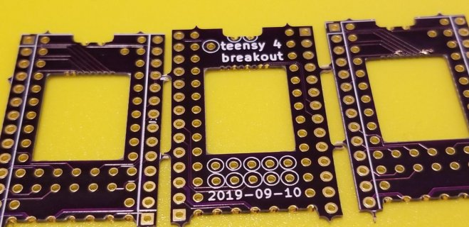
Mine arrived today. Man those 1mm holes look small.
Mine arrived today. Man those 1mm holes look small.
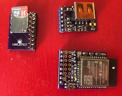
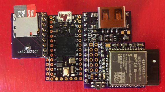
Good work - fast. So a CAP isn't called for to support the SD power needs? Loglow breakout has 3 caps - one for USB - I assumed one was for SD.
6.6.3 Current Consumption
The current consumption is measured by averaging over 1 second.
• Before first command: Maximum 15 mA
• During initialization: Maximum 100 mA
• Operation in Default Speed Mode: Maximum 100 mA for SDSC and SDHC
  100mA (XPC=0) or 150mA (XPC=1) for SDXC
• Operation in High Speed Mode: Maximum 200 mA
• Operation in UHS-I Mode: Maximum 400mA (UHS50,DDR50) or 800mA (UHS104)
• Operation with other functions: Maximum 500 mA.
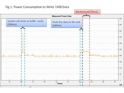
Modern uSD cards can have large current pulses. 512KB flash pages are common and write times must be fast to achieve 100 MB/sec rates. so large pulses can occur.
...
A Teensy 4.x with a uSD socket and 1.8V signal capability will need to supply 800 ma of 3.3V in UHS104 mode.
I hope Paul produces a T 4.x capable of UHS104. I designed SdFat for Teensy 4.0 to do infinite size writes since the uSDHC controller can support infinite write sequences.
Yeah, they are. With ample flux and a little cleanup from excess solder with a braid mine went pretty easy.
What size/type capacitors are people using for the USB host and SD cards? Are there other protections that we should be thinking about? Do we need diodes in the USB to prevent reverse current flow?. How about the ability to provide separate power and regulate it to 5v? Obviously with some of these things, you would need to go to daughter cards to add the extra components. I saw people designing the daughter cards, but I wasn't sure whether they had been used or not.

Seeing as I already have the board in KiCad I'll take a shot at playing with the layout, drill size, pad sizes, etc
Seeing as I already have the board in KiCad I'll take a shot at playing with the layout, drill size, pad sizes, etc
Sorry about that, guys!
I suspect that it's related to the thinner material. I haven't yet ordered the thinner ones, I'll do it now, along with another set of thicker ones.
@DerekR: The OSHPark folks are really helpful. Please let us know if you hear any feedback from them.
Thanks for your patience.
Hi Dean,
That's not unexpected, and an unfortunate example of why we currently aren't able to guarantee castellated areas on a design.
Each fabrication run is subject to interpretation by the operator at the time, so even if one returns as expected, a subsequent run on the very same service may not. It's possible the fab operator handling that 0.8 mm thick batch deemed those pads more likely a header, or simply decided that attempting a cutout there too risky. Via plating and pads, especially on smaller features may randomly be torn by the milling process.
So in the end, while we do allow the attempt and often it succeeds when following the guidelines, there's always a chance it may not work and why we don't currently guarantee them.
Chris
If there are favorite sites that discuss things like flux, etc. it might be helpful for those of us whose knowledge ends with which part of the of the soldering iron to hold.
I fear already that mine will look the same when they’ll arrive here in France in a few days... Why don’t they use a precise laser to do the cut-outs?
I've been looking at your breakout board for a week or so (along with the USB host companion board), waiting to finish a design of my own before ordering them all from OSH Park.
Should I order it in 1.6mm, or are these also hit-and-miss ?


