
You are using an out of date browser. It may not display this or other websites correctly.
You should upgrade or use an alternative browser.
You should upgrade or use an alternative browser.
Eagle library with Teensy 3.0 footprint
- Thread starter UnaClocker
- Start date
- Status
- Not open for further replies.
Constantin
Well-known member
I tried the above posted Eagle lbr in Eagle 5.11, it says that the lbr contains invalid data and doesn't load. Any reason why? Or is it just due to using an older/newer version?
Most likely, it's because I was using eagle 6. Thus, I'd recommend downloading the latest version of eagle and going from there. Some of the changes in eagle from version 5 to six include the ability to have multiple pins with the same signal (for example appending GND to three pins vs having three pins with names that are close but not the same (GND1 GND2 and so on). That's the likely source of error.
PaulStoffregen
Well-known member
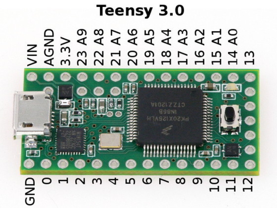
there are 24/34 I/O pins. Where is the Truth?
On the pinout reference card that ships with every single Teensy3.
You can also view it and get the PDF files here:
http://www.pjrc.com/teensy/pinout.html
Constantin
Well-known member
So, it's only 24? But in Eagle's parts there is a scheme with 34 pins.
Take another look at both sides of the Teensy 3 photos that Paul has provided here for the front and here for the back. Specifically, take a look at the back of the board for the discussion that follows.
The board that Paul designed has one row of holes around the perimeter. Additionally, there are pin holes inside that. Then, there are pads, not holes, for a pin header that you can purchase at digikey. Here is a link to a selection of them. You can solder them on pretty easily and the name of the game is to select a SMD header that has the same pin length as the regular through-hole pins you are using. The 'extra' holes of the 34 pin design conform to the expected locations of the pins coming out of the SMD header.
The key to soldering them on is to maintain the same 0.1" grid spacing as the rest of the pins in the Teensy 3 layout. I suggest using the usual technique of tacking on one corner carefully, then the opposite corner, making sure they're well-aligned, and then soldering on the other pins first. I'd solder this header after attaching a RTC crystal (they are very close) but before attaching the outer row pins.
If you wonder why there are pads vs. holes on the underside, it comes back to (IIRC) a decision that Paul made when the chip that he was supposed to be able to use became unavailable and he then switched to a 'bigger' chip that was not under development. The form factor of the board was already established so the only way that Paul could accommodate the additional pins of the physically larger replacement chip in use today was to put pads on the underside. HTH.
PS: It will be very interesting to see how Paul will differentiate the upcoming Teensy 3++ from the already awesome 3. I have no idea re: the details but it's going to be very very cool, I'm sure!
Last edited:
PaulStoffregen
Well-known member
DrMefistO, do you actually have a Teensy 3.0 board? If so, just turn it over and look at the bottom side.
The reality is the 24 pins on the edges of the board are much easier to access. The 10 other digital pins, plus 2 more analog, are only available at the bottom side of the PCB. In designing any product, there are always trade-offs. With Teensy, an important goal has always been small size. If those 12 signals came to the edges of the board, it would need to be 43% larger. The vast majority of projects do not need more than 24 pins. Just look at how many projects work with Arduino Uno, which has 20 pins. But this chip has those extra 12 signals. I put those pads on the bottom side so you can get access to those other 12 signals, if you really need them. There are also 2 more analog, and the voltage ref, on a 2nd row of pads.
There truly are 34 digital I/O pins. There's also 4 more analog input only pins, so really there's a total of 38 signal pins. But those other 4 aren't "I/O", since you can't use them for output and as inputs, they're only for analog.
It sounds like you might be unhappy with the product's description? That too is a design trade-off, with a triple goal. #1: provide as much info as possible, #2: keep it brief, mentioning only the most important info, and #3: show the product's selling points. Certainly the goal is NOT to mislead you or anyone. But on a summary page, there isn't room for every little detail. That's why there's reference section. This is common practice for pretty much all technical products.
Every Teensy 3.0 has that printed reference card included. It's full color printed on both sides, using those 2 PDF files. To see the info about the other 12 signals on the back side, all you have to do is flip the card over. Or if the real Teensy3 is in your hand, just look at the bottom side. Since there's no parts on the bottom, pretty much all the space that isn't pads for connections is printing to label everything.
Thanks HWGuy for the reply. The A14/Reset won't be an issue for my design. Perhaps a better question. I am having trouble wrapping my head around the package for the Teensy in Eagle. What I am looking for is to be able to place 2 14-pin female headers on the board so I can replace/repurpose the Teensy. As I understand the existing package it provides pin locations for soldering a Teensy w/ pin headers directly onto the board. Can I leave the package as is and simply solder on female headers onto my board and male pins onto the Teensy? I'm not interested in the 5 pins at the foot of the 3.2, just the 2 side rows of 14 pins.
Yes.What I am looking for is to be able to place 2 14-pin female headers on the board so I can replace/repurpose the Teensy. As I understand the existing package it provides pin locations for soldering a Teensy w/ pin headers directly onto the board. Can I leave the package as is and simply solder on female headers onto my board and male pins onto the Teensy?
Sparkfun does the same with the Teensy Arduino Shield Adapter https://www.sparkfun.com/products/13288
Constantin
Well-known member
Hi guys,
I noted some errors in the LC board, i.e. still using the AGND pin when there isn't one. Also found that "17 @ VIN" will not display (Pin name).
Both have been corrected. This ZIP contains both the finished board outlines for the 3.x and LC series, as well as the chips needed to make Teensy's yourself.
Now I get to hunt for the older files... oh well!
Attachments
Last edited:
Constantin
Well-known member
Thanks for making and maintaining these!
One thing I noticed was that as discussed in the recent thread about master/slave SPI, MOSI and MISO don't exist on the Teensy3 and these should probably be relabelled as SOUT and SIN next time you're doing revisions.
Great suggestion, but looking over the pinout card, I didn't see those terms used. Did you mean DOUT and DIN?
Great suggestion, but looking over the pinout card, I didn't see those terms used. Did you mean DOUT and DIN?
The SPI section of the reference manual uses SIN and SOUT, but DIN and DOUT is better if that's what the reference card uses.
Constantin
Well-known member
There are many approaches to doing this.
One involves the use of two dual-row headers, where the 'inner' set of pins are bent 90* as discussed here.
Or, you can buy an 2x7 SMD pin header and solder that on.
Or, you can buy one of the Teensy pin breakout boards on Tindie.
One involves the use of two dual-row headers, where the 'inner' set of pins are bent 90* as discussed here.
Or, you can buy an 2x7 SMD pin header and solder that on.
Or, you can buy one of the Teensy pin breakout boards on Tindie.
Reversed MOSI/MISO pins in library?
I just a got a batch of boards back that refused to work. Ultimately I think it traces back to MISO/MOSI being reversed in the Teensy_3.1_DIL package of the library "Teensy_3_and_LC_Series_Boards_v1.1".
- published pinouts on this site say MOSI (DIN) is pin 12 on the Teensy 3 series
- Eagle footprint for device "Teensy_3.1_DIL" says MISO is Pin 11
Could someone with a higher knoweldge have a look and see if the library is OK? It's entirely possible I am worng or made some mistake along the way, although breaking traces and reversing the two pins made the boards work!
I'm loving the Teensy BTW, thank you. Thank you also for the library, which saved a lot of time!
D
Pin 11 is DOUT -> MOSI (Master Out Slave In)
PIN 12 is DIN -> MISO (Master In Slave Out)
The Teensy_3.1_DIL package is ok.
edit:
note: this applies only to the Teensy in SPI master mode, in slave mode MOSI/MISO are reversed:
Pin 11 is DOUT -> MISO (Master In Slave Out)
PIN 12 is DIN -> MOSI (Master Out Slave In)
PIN 12 is DIN -> MISO (Master In Slave Out)
The Teensy_3.1_DIL package is ok.
edit:
note: this applies only to the Teensy in SPI master mode, in slave mode MOSI/MISO are reversed:
Pin 11 is DOUT -> MISO (Master In Slave Out)
PIN 12 is DIN -> MOSI (Master Out Slave In)
Last edited:
Constantin
Well-known member
OK, here is a Eagle library update with a preliminary addition of the 3.5 and 3.6 series teensy boards. If someone could have a look at them to see if they match up, that would be great.
The main differences I can divine between the 3.6 and the 3.5:
* D+/D- is swapped for A25/A26 plus VUSB vs. NC for USB header
* No CAN1 serial on 3.5
* No I2C Channel 3 on 3.5
* No Touch pins on 3.5
* Some PWM pin differences.
Is that it?
Also, is that "DO" on the Debug header or DD, D0, etc?
No updates to the Teensy DIY library yet because I am unaware of any schematics being posted yet (hint hint!)")
EDIT: the attached file has been updated from v1.2 to 1.3 to reflect Hw guys excellent feedback. Many thanks!
EDIT: Now updated again with Franks correction - thank you!
The main differences I can divine between the 3.6 and the 3.5:
* D+/D- is swapped for A25/A26 plus VUSB vs. NC for USB header
* No CAN1 serial on 3.5
* No I2C Channel 3 on 3.5
* No Touch pins on 3.5
* Some PWM pin differences.
Is that it?
Also, is that "DO" on the Debug header or DD, D0, etc?
No updates to the Teensy DIY library yet because I am unaware of any schematics being posted yet (hint hint!)
EDIT: the attached file has been updated from v1.2 to 1.3 to reflect Hw guys excellent feedback. Many thanks!
EDIT: Now updated again with Franks correction - thank you!
Attachments
Last edited:
defragster
Senior Member+
OK, here is a Eagle library update with a preliminary addition of the 3.5 and 3.6 series teensy boards.
Constantin: I won't link this to K66_post_8 unless you say so since you have it marled preliminary - if you want it linked to #45 let me know and I'll make it sticky on K66 thread.
Jeez - I haven't seen a schematic either
- maybe there is one in the worksEagle files for T3.6:
- Pin 13: SCK0
- Pin 16: +PWM
- Pin 32: -T -PWM +A13 +SCK1 +TX4
- Pin 33: -A15 +A14
- Pin 34: -A5 + A15
The pins from the larger smd header are swapped. (GND5, 3.3V2, 40 - 53)
The USB pin header is at the wrong position, the distance from the left row is not 2.54mm. In this post the distance is marked with 3.175mm (3.18mm): https://forum.pjrc.com/threads/34808-K66-Beta-Test?p=112826&viewfull=1#post112826
I have no experience with the 2nd USB port, but I think it's not good to connect both VUSB.
KurtE
Senior Member+
Looks like HWGuy pretty good look through the pin. As he mentioned, I would not connect the VUSB to the +5v connector on the USB Host connector. Not sure exactly what it is connected to, but it is not a 0 resistance between the pins.
I am not an expert in Eagle, much prefer Diptrace, so I converted it to Diptrace to take a look. For me, I prefer to actually split up the duplicate pins as at least with Diptrace, if I connect them all up to each other in the components and then use the component on a board, the system will expect that I need to run etch between each of these pins. So I prefer to choose which ones I wish to use or not use.... But again maybe Eagle is different.
I am not an expert in Eagle, much prefer Diptrace, so I converted it to Diptrace to take a look. For me, I prefer to actually split up the duplicate pins as at least with Diptrace, if I connect them all up to each other in the components and then use the component on a board, the system will expect that I need to run etch between each of these pins. So I prefer to choose which ones I wish to use or not use.... But again maybe Eagle is different.
Constantin
Well-known member
Hi guys, first of all, many thanks in particular to HW guy for the look over!
I have updated the library, it is attached up above. The VUSB issue will be revisited once we get a schematic, I guess! I've left VUSB and 5V connected for now.
Also, all erroneous references to Touch have been removed from the Teensy 3.5 schematics.
I have updated the library, it is attached up above. The VUSB issue will be revisited once we get a schematic, I guess! I've left VUSB and 5V connected for now.
Also, all erroneous references to Touch have been removed from the Teensy 3.5 schematics.
Last edited:
defragster
Senior Member+
OK, here is a Eagle library update with a preliminary addition of the 3.5 and 3.6 series teensy boards. If someone could have a look at them to see if they match up, that would be great.
Also, is that "DO" on the Debug header or DD, D0, etc?
EDIT: the attached file has been updated from v1.2 to 1.3 to reflect Hw guys excellent feedback. Many thanks!
On my Beta boards silkscreen looks like a "DD"
I'm linking that 'Eagle' post to K66_Beta post_8 since is got some review.
- Status
- Not open for further replies.