Interrupt on Rising and Falling on the same pin

Status
Not open for further replies.
Can you say what are the characteristics of the ring buffer implementation that guarantee this is safe?

Pushing is only done in the interrupt and won't be interrupted. Popping is done by the lockedPop() method which will simply disable interrupts while it pops the value. Not the most efficient way to do it but good enough for this test.

Here the relevant code in the decoder: https://github.dev/luni64/mancheste...71aa832da800/receiver/src/decoder.cpp#L37-L45 and here the lockedPop() method: https://github.dev/luni64/mancheste...eiver/lib/RingBuffer-1.0.3/src/RingBuf.h#L192
 
Pushing is only done in the interrupt and won't be interrupted. Popping is done by the lockedPop() method which will simply disable interrupts while it pops the value.

Okay, good to know. I guess my question is specific to FreqMeasureMulti, whose read() function does not disable interrupts, as shown below. I've used this a lot, so as far as I know it works correctly with writes from the ISR and reads from non-ISR level with no disabling interrupts. FreqMeasureMulti actually does save both the period and the edge level to its ring buffer, so it seems to be equivalent to what you've done, but for FTM.

Code:
uint32_t FreqMeasureMulti::read(void)
{
	uint32_t head = buffer_head;
	uint32_t tail = buffer_tail;
	if (head == tail) return 0xFFFFFFFF;
	tail = tail + 1;
	if (tail >= FREQMEASUREMULTI_BUFFER_LEN) tail = 0;
	uint32_t value = buffer_value[tail].count;
	last_read_level = buffer_value[tail].level;
	buffer_tail = tail;
	return value;
}
 
I guess my question is specific to FreqMeasureMulti, whose read() function does not disable interrupts, as shown below. I've used this a lot, so as far as I know it works correctly with writes from the ISR and reads from non-ISR level with no disabling interrupts.

Circular buffer with head and tail index / pointer is considered "lock free" if writing to the buffer only modifies the head and reading from the buffer only modifies the tail, and the actual buffer access is completed before change to the head / tail index. Here's one article which explains. Scroll down to the end and start reading just after the last code sample.

https://www.downtowndougbrown.com/2013/01/microcontrollers-interrupt-safe-ring-buffers/

This approach has a well known limitation. One space in the buffer can never be used. So if you have a 64 byte buffer, it will be full when holding only 63 bytes. Most people consider this to be an acceptable loss, though it's often glossed over in these sorts of articles.

Thanks so much. Nice reference, too, and you're right about "glossing over" the N-1 limit. The condition head==tail is used to determine if the buffer is empty, which would also be true of the buffer of size N contained N values, so it has to be one or the other.

As an aside, I've been using a ring buffer implementation for many years that allows a buffer of size N to contain N values, but in addition to head and tail, it maintains a count field that can range from 0-N. The get() function contains the following comment:

q->count is altered by the associated function q_put(), which may operate at interrupt level. If p->count-- is interruptible, it must be bracketed by INTS_OFF and INTS_ON code.

I've been using the code without disable/enable interrupts on 683xx and Coldfire family processors for many years, and at one point I did confirm that p->count-- was a single instruction, which I took to mean uninterruptible. I know so little about ARM and cache and other features that might be involved in making such a determination for Teensy. Do you think count-- and ++count would be interruptible on Teensy? I like the idea of just limiting the number of values to N-1 so it's not a concern.
 
Generally speaking: (meaning I've not looked at that library)

Pointers to a buffer must be accessed/updated in critical regions, or inherently act like the event-counter synchronization primitive.

[ And of course you may also need to flush caches (if cachable memory is being shared between code and DMA) ]

Event-counters are only ever written by one thread/process/context, and a circular buffer can use one for the insert point,
one for the extract point, owned by producer and consumer respectively. Event counters notionally grow indefinitely, so you'd
take the modulus with the buffer size to turn one into a buffer index.

So you might call event counters for a buffer "elements_inserted", "elements_extracted", and your buffer checks look like
Code:
bool empty () { return elements_extracted == elements_inserted; }
bool full() { return elements_inserted == elemented_extracted+SIZE ; }
These tests can guard operations that extract and insert respectively.

https://www.cl.cam.ac.uk/research/srg/netos/projects/archive/pegasus/papers/jsac-jun97/node19.html
https://en.wikipedia.org/wiki/Critical_section
 
So you might call event counters for a buffer "elements_inserted", "elements_extracted", and your buffer checks look like
Code:
bool empty () { return elements_extracted == elements_inserted; }
bool full() { return elements_inserted == elemented_extracted+SIZE ; }
These tests can guard operations that extract and insert respectively.

If by critical region you mean a region that uses a lock, such as disable/enable interrupts, that's what we're working around with the interrupt-safe strategy. It's lock-free, and buffer head, tail, and size are sufficient to determine empty/full. See the link in Paul's post for the details.
 
What I was trying to say was that my question to Paul had been what were the characteristics of lock-free ring buffers, which by definition do not have critical sections. His reference was to a good explanation of the "rules" for creating a ring buffer that can be used to communicate data from interrupt to non-interrupt level without disable/enable interrupts, which should mean it would also be thread-safe even with a preemptive RTOS.
 
Alright, so I've been churning away at the code posted by @luni back in post #17. I've also read all the posts after that but as a relative beginner I have to admit I understand about 20% of it right now.

The code posted by Luni works exactly as he stated, but what it didn't accomplish 2 things which were important to me in my application:
1) Identify the start bit and anchor on that, taking 21 samples following
2) Handle variable number of edge transitions.

In manchester encoding, there is not a known number of edges for an unknown data packet (even with a known length). This is because there are more transitions in a data block of 111111111111111111111 than there are in 101010101010101010101. Specifically in my case, there is an upper bound of 46 edge transitions per packet (including start and stop bits) and a lower bound of 25 edge transitions.

I tried to modify luni's code to do the following:
1) After 2 samples, check the difference in time. If the difference represents a start bit, then continue, if not, roll the index back to 1 so we can check the next sample. This means no data is added to cap_vals[] until the time stamps at [1] and [2] have a difference of ~394 clock cycles indicating a start bit. Index [0] is left at 0 to avoid seg faults when calculating the delta time.
2) Keep recording until a stop bit is found (delta is approximately 57 clock cycles).
3) Adjust the print statement in loop() to use cap_index to print a variable number of time deltas, always starting with a start bit and ending with a stop bit.

I have run into nonstop issues implementing these changes and I just don't understand why. Am I trying to do something in the ISR that is not allowed? Either the code won't trigger my conditionals, or the serial stream just cuts out for many seconds at a time then spits jibberish.

Code:
#include "Arduino.h"

//

//constexpr unsigned maxEdges = 14;
volatile uint32_t cap_index;
volatile uint16_t cap_vals[100];

IMXRT_TMR_CH_t& ch = IMXRT_TMR1.CH[2]; // TMR1_2 -> input pin 11

bool recording = false;

void onCapture()
{
    
    ch.SCTRL &= ~(TMR_SCTRL_IEF); // no need to check which flag was set since we only enabled IEF
    if (recording)
    {
        
        cap_index++; //start index @ 1
        
        cap_vals[cap_index] = ch.CAPT;  // store the captured value
        
        uint16_t cap_delta = cap_vals[cap_index] - cap_vals[(cap_index-1)];
        
        if (cap_index == 2){
            if ((cap_delta < 392) || (cap_delta > 396)){ //Not a start bit
                cap_vals[1] = cap_vals [2];
                cap_index = 1;
            }
        }
        if (((cap_index > 2) && ((cap_delta >= 55) || (cap_delta <= 59))) || cap_delta == 70 ){ //Stop bit found
            recording = false;
        }
    }
    asm volatile("dsb"); // wait for clear  memory barrier
}


void initTimer()
{
    cap_vals[0] = 0;
    cap_index   = 0;

    *(portConfigRegister(11)) = 1;        // Alt1, use pin11 as input to TMR1_2
                                          //
    ch.CTRL  = 0;                         // stop timer
    ch.SCTRL = TMR_SCTRL_CAPTURE_MODE(3); // capture at rising and falling edges 
    ch.SCTRL |= TMR_SCTRL_IEFIE;          // enable input edge flag interrupt
    ch.LOAD = 0;

    attachInterruptVector(IRQ_QTIMER1, onCapture);
    NVIC_ENABLE_IRQ(IRQ_QTIMER1);

    ch.CTRL = TMR_CTRL_CM(1) | TMR_CTRL_PCS(8 + 0) | TMR_CTRL_SCS(2); // source: peripheral clock, prescaler 0, use counter 2 input pin for capture
}

void setup()
{   
    Serial.begin(9600);
    Serial.println("start");
    initTimer();
    recording = true;
}

void loop()
{
    if (!recording)
    {
        for (unsigned i = 1; i < cap_index; i++)
        {
            uint16_t x;
            if (cap_vals[i] > cap_vals[i-1])
            {
                x = (cap_vals[i] - cap_vals[i-1]);
            }
            else
            {
                x = (uint16_t)0xFFFF - (cap_vals[i-1] - cap_vals[i]);
            }
            //Serial.printf("%.2f ", 1E6 * x / F_BUS_ACTUAL);
            Serial.print(x);
            Serial.print(" ");
        }
        Serial.println();
    }
    cap_index = 0;
    recording = true;
}

Is there a better way to do this? I tried to understand some of the follow-up comments about protected ring buffers, but I'll be honest that most of it went right over my head.

Thanks!

EDIT:

Here is a sample of the serial monitor output of Luni's code when talking to my encoder. Notice how there is no pattern. I'd like to see each line start with 2.63 (the start bit) and end with 0.38 (the stop bit). 16.99 represents the dead time between packets.

Code:
0.49 0.51 0.49 0.50 0.50 0.50 0.49 0.51 0.49 0.51 0.49 0.51 0.49 
0.99 1.01 0.99 1.01 0.49 0.51 0.99 0.51 0.49 0.51 0.49 0.51 0.49 
1.01 0.49 0.51 0.99 1.01 0.99 0.38 16.99 2.63 0.99 0.51 0.49 0.51 
0.49 0.51 0.49 0.51 0.49 0.51 0.49 0.51 0.49 0.51 0.49 0.51 0.49 
0.99 1.01 0.99 1.01 0.49 0.51 0.99 0.51 0.49 0.51 0.49 0.51 0.49 
1.01 0.49 0.51 0.99 1.00 1.00 0.38 16.99 2.63 0.99 0.51 0.49 0.51 
0.51 0.49 0.51 0.49 0.51 0.49 0.51 0.49 0.51 0.49 0.51 0.49 0.51 
0.99 1.01 0.99 1.00 0.49 0.51 0.99 0.51 0.49 0.51 0.49 0.51 0.49 
1.01 0.49 0.51 0.99 1.01 0.99 0.38 16.99 2.63 0.99 0.51 0.49 0.51 
0.49 0.51 0.49 0.51 0.49 0.51 0.49 0.51 0.49 0.51 0.49 0.51 0.49 
0.99 1.01 0.99 1.01 0.49 0.51 0.99 0.51 0.49 0.51 0.49 0.51 0.49 
1.01 0.49 0.51 0.99 1.01 0.99 0.38 16.99 2.63 0.99 0.51 0.49 0.51 
0.49 0.51 0.49 0.51 0.49 0.51 0.49 0.51 0.49 0.51 0.49 0.51 0.49 
0.99 1.01 0.99 1.01 0.49 0.51 0.99 0.51 0.49 0.51 0.49 0.51 0.49 
1.01 0.49 0.50 0.99 1.01 0.99 0.39 16.99 2.63 0.99 0.51 0.49 0.51 
0.49 0.51 0.49 0.51 0.49 1.00 0.99 0.51 0.49 1.01 0.49 0.51 0.99 
0.51 0.49 0.51 0.49 1.01 0.99 1.01 0.99 0.38 16.99 2.63 0.99 0.51 
0.49 1.01 0.99 1.01 0.99 1.01 0.49 0.51 0.99 0.51 0.49 0.51 0.49 
0.51 0.99 1.01 0.49 0.51 0.99 1.01 0.99 0.38 16.99 2.63 0.99 0.51 
0.51 0.49 0.51 0.49 0.51 0.49 0.51 0.49 0.51 0.49 0.51 0.49 0.51 
1.01 0.99 1.01 0.99 1.01 0.49 0.51 0.99 0.51 0.49 0.51 0.49 0.51 
0.99 1.01 0.49 0.51 0.99 1.01 0.99 0.38 16.99 2.63 0.99 0.51 0.49 
0.51 0.49 0.51 0.49 0.51 0.49 0.51 0.49 0.51 0.49 0.51 0.49 0.51 
0.49 1.01 0.99 1.01 0.99 1.01 0.49 0.50 0.99 0.51 0.49 0.51 0.49 
0.51 0.99 1.01 0.49 0.51 0.99 1.01 0.99 0.38 16.99 2.63 0.99 0.51 
0.51 0.49 0.50 0.50 0.50 0.49 0.51 0.49 0.51 0.49 0.51 0.49 0.51 
1.01 0.99 1.01 0.99 1.01 0.49 0.51 0.99 0.51 0.49 0.51 0.49 0.51 
0.99 1.01 0.49 0.51 0.99 1.01 0.99 0.38 16.99 2.63 0.99 0.51 0.49 
0.51 0.49 0.51 0.49 0.51 0.49 0.51 0.49 0.51 0.49 0.51 0.49 0.51 
0.49 1.01 0.99 1.01 0.99 1.01 0.49 0.51 0.99 0.51 0.49 0.51 0.49 
0.51 0.99 1.01 0.49 0.51 0.99 1.00 0.99 0.39 16.99 2.63 0.99 0.51 
0.51 0.49 0.51 0.49 0.51 0.49 0.51 0.49 0.51 0.49 0.51 0.49 0.51 
1.01 0.99 1.00 1.00 1.00 0.49 0.51 0.99 0.51 0.49 0.51 0.49 0.51 
1.01 0.49 0.51 0.99 1.01 0.99 0.38 16.99 2.63 0.99 0.51 0.49 0.51 
0.49 0.51 0.49 0.51 0.49 0.51 0.49 0.51 0.49 0.51 0.49 0.51 0.49 
0.99 1.01 0.99 1.01 0.49 0.51 0.99 0.51 0.49 0.51 0.49 0.51 0.49 
1.01 0.49 0.51 0.99 1.01 0.99 0.38 16.99 2.63 0.99 0.51 0.49 0.51 
0.49 0.51 0.49 0.51 0.49 0.51 0.49 0.51 0.49 0.51 0.49 0.51 0.49 
0.99 1.01 0.99 1.01 0.49 0.51 0.99 0.51 0.49 0.51 0.49 0.51 0.49 
1.00 0.50 0.50 0.99 1.01 0.99 0.39 16.99 2.63 0.99 0.51 0.49 0.51 
0.51 0.49 0.51 0.49 0.51 0.49 0.51 0.49 0.51 0.49 0.51 0.49 0.51 
1.00 1.00 0.99 1.01 0.49 0.51 0.99 0.51 0.49 0.51 0.49 0.51 0.49 
1.01 0.49 0.51 0.99 1.01 0.99 0.38 16.99 2.63 0.99 0.50 0.50 0.50 
0.51 0.49 0.51 0.49 0.51 0.49 0.51 0.49 0.51 0.49 0.51 0.49 0.51 
0.99 1.01 0.99 1.01 0.49 0.51 0.99 0.51 0.49 0.51 0.49 0.51 0.49 
1.01 0.49 0.51 0.99 1.01 0.99 0.38 16.99 2.63 0.99 0.51 0.49 0.51 
0.49 0.51 0.49 0.51 0.49 1.01 0.99 0.51 0.49 1.01 0.49 0.51 0.99
 
I haven’t reviewed your code, but even without doing so, I recommend putting all of the Manchester-specific logic in the decoder. Let the receiver code be an edge data logger useful for many things, and have a Manchester decoder, a UART decoder, etc. This will also avoid lengthening the ISR and subtle bugs.
 
Alright, so I've been churning away at the code posted by @luni back in post #17. I've also read all the posts after that but as a relative beginner I have to admit I understand about 20% of it right now.

The code in #17 was just a first trial. The code in #19 detects the start bit and decodes bytewise. You don't need to fiddle around with the interrupt code, the decoder class handles all this. Also the decoder doesn't depend on the number of edges since, as you said, this is not defined in the manchester encoding. The decoder happily reads bits until it detects an unusual timing (e.g your 24µs break). In that case it waits for the next start bit.

So, I'd start with the code in #19 and change it accordingly. You probably only need to adapt the decode function (see here https://github.com/luni64/mancheste...211471aa832da800/receiver/src/decoder.cpp#L47)

I assumed a T of 500ns (change to your need in line 49) and a startbit length of 3500ns -> Adjust to your need in line 58. The current code will store the read bits in bytes as long as correctly timed edges come in. If not it waits for the next start bit. -> You probably need to change the code such that it stores the result in 32bit variables.

Let me know if you need help with this. It would be good if you could post a few examples showing the timing (e.g. bit pattern and corresponding scope trace) of what your device would typically send.
 
I'll need to take some time to dive into #19 then. Let me have a go at it, and if you don't mind, I'll bug you if I get stuck. I have a lot of learning to do and unfortunately the only way I learn is to suffer through it.

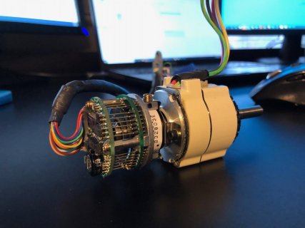
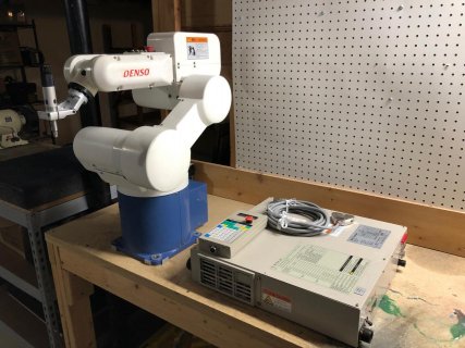
In the meantime, I'll share some project specifics. I am working on a 1999 Denso industrial robot as a hobby. If I can get it running I might make silly tasks for it, or bring it to local high schools/FIRST robotics to get kids interested in STEM topics. The controller is currently dead. I am working in parallel to get that running, but if I cannot use it, I need to be able to run the motors on servo drives I own. These encoders are Tamagawa brand TS5643N151 series serial encoders (battery back absolute 11 bit single turn and 13 bit multiturn). See picture below from a dead motor. My servo drives talk to Tamagawa serial encoders, but a different kind with a different data format. I would like to have some go-between interface board that intercepts the data from the encoder (which is streamed continuously) and saves it in memory. Then when the drive requests the data, the interface board will pull the data it needs from memory and format a proper reply to the drive. If all goes as I hope, the drive will have no idea it is talking with a different encoder.

image023.jpg

image083.jpg

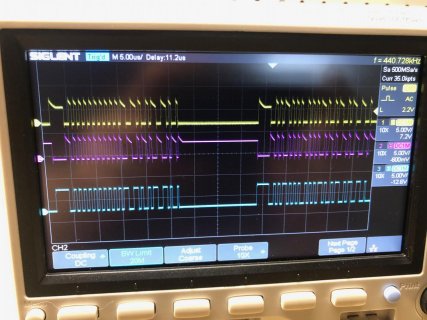
The data is transmitted from the encoder at 2 Mbps (1M baud) manchester serial. A full transmission is two burst packets back to back. The first contains the single turn data (the motor shaft angle) and a couple bits of the multiturn data (the motor revolution counter). The second packet is the rest of the multiturn data and 6 status flags. Each packet has a 3 bit CRC using a 1011 polynomial. Below is a burst captured on the scope. Yellow and Pink are the differential signals of the RS422 driven line, and blue is what the processor is receiving after an AM26C32I RS422 differential receiver and a 5V to 3.3V level shifter.

image109.jpg

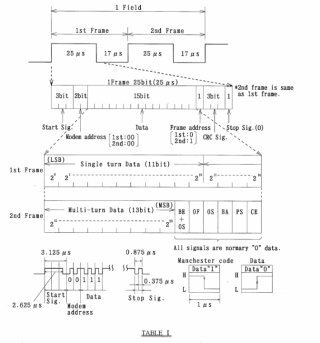
This excerpt from the encoder manual shows the data format. Specifically the payload of the packet is 18 bits with a 3 bit CRC. This is not arranged in standard 8 bit bytes and it is LSB rather than MSB, so I'll need to do some bit shifting and bit inversion after the data is captured to be able to decode it into something intelligible. Notice how the multiturn data is split between packet 1 and 2. After both packets are transmitted, packet 1 is transmitted again. I've also attached the full encoder specification, although it doesn't give much more data than what the image shows.

View attachment TS5643N100.pdf

image126.png

So I'm trying to break the project down into smaller chunks but the 3 main parts I see are:
1) Read the robot encoder manchester serial, save data to memory
2) Read the robot encoder quadrature signals. This increases the encoder single turn resolution to 13 bit and gives redundancy (incremental count and serial data can cross check eachother). Haven't messed with this but I know the Teensy has a hardware quadrature decoder
3) Read the drive request packet (NRZ serial, 2.5 Mbps, NOT manchester), and respond with the proper payload using the data from items 1 and 2.

The interface board can never miss a count from item 2 (this should be OK since it is hardware) and can't miss a response to the drive, but can occasionally miss serial packets from the encoder since the data will be repeated at the next transmission.
 
Also apologies in advance if any of my questions are those of a neophyte. I mostly do mechanical and industrial electrical work, so even finding the download button on GitHub can be a challenge for me. I have a few years experience with an arduino Uno/Mega, a little with an RPi, even less with a STM Nucleo on MBed, and about a week with the Teensy. This high speed stuff is a challenge for me to wrap my head around and the manual for this processor is daunting (I understand like 1% of it :eek:)

Really appreciate everyone's involvement. I can already tell this forum is an amazing community.
 
Still messing around with the code.. Had one somewhat unrelated question. I'm used to, when downloading Arduino libraries, to download a ZIP file, extract it, and put the folder in the "libraries" folder. This didn't seem to work and threw a bunch of errors complaining that the libraries here missing header files.

Anyways, I remembered there was a way to add tabs to Arduino projects, and once I copied and pasted all of the code from luni's library in there, it compiled. Problem is, I'm not exactly sure what the arduino tabs are or what they do... Can anyone explain why putting it in libraries didn't work, but this did?

image160.png


Unsurprisingly, this code didn't immediately work for my encoder (since this code looks for packets with 1 byte per burst, and my transmissions need to be decoded bitwise and have the data manipulated. I am working on learning and understanding the code so I can modify it as needed.
 
Still messing around with the code.. Had one somewhat unrelated question. I'm used to, when downloading Arduino libraries, to download a ZIP file, extract it, and put the folder in the "libraries" folder. This didn't seem to work and threw a bunch of errors complaining that the libraries here missing header files.

Sorry if I confused you. The code on Github is just a snapshot of my development files to demonstrate how such a thing can be done. It currently is not meant to be a library. There are two folders, the sender folder unsurprisingly contains the code I used on a T4.0 to generate the Manchester pattern. The code in the receiver folder decodes the generated pulsetrain on a seperate T4.1.

Anyways, I remembered there was a way to add tabs to Arduino projects, and once I copied and pasted all of the code from luni's library in there, it compiled
Perfect, that's the way to do it.

Problem is, I'm not exactly sure what the arduino tabs are or what they do...
If you have more than one file in a sketch folder the IDE displays each file (well, *.cpp, *.h and *.ino) in its own tab. Nothing special about this. Sorry again if this confused you. Since you are fiddling around with interrupts which is pretty high level, I simply assumed that you are familiar with multi file sketches.
You can of course have all code in one huge *.ino file but that would get messy quickly. Since you come from ME: Imagine designing a motor using only one huge flat design file / BOM without subassemblies or any other functional structure. You can think of the *.cpp files as subassemblies which provide a dedicated functionality, the corresponding *.h files as a description of the subassembly to other designers and the compiler. Hope that helps. As always, you'll find much better explanations about this online...

Unsurprisingly, this code didn't immediately work for my encoder (since this code looks for packets with 1 byte per burst, and my transmissions need to be decoded bitwise and have the data manipulated. I am working on learning and understanding the code so I can modify it as needed.

Yes, you need to adapt this part. In any case this will be a good exercise, it doesn't contain hard to understand low level stuff.

I meanwhile read your encoder datasheet and did a simulator to generate such pulse trains. Here the output it produces. My cheap $10 Logic analyzer is able to interpret the code, so it seems to be valid Manchester. Analyzing the bits showed that it composes the frames as described in your datasheet:

Screenshot 2022-03-03 201508.jpg

I'll use this simulator to adapt the decoder accordingly. But, I have the impression that you want to learn how to do this stuff yourself. So, I won't spoil your fun and only post it when you are stuck :)
 
Luni,

No worries at all. I have a decently wide knowledge of what a microcontroller can do, and why you'd want to do it that way (interrupts, DMA, non-blocking functions, etc.) but I just don't program enough to be confident implementing everything. I can put together a project from common libraries pretty easily, but something like this which doesn't have a standard library gets a bit over my head. As do low level function calls (how do you even begin learning this? Look like gibberish :)) I certainly didn't expect you to write my code for me or make a ready to use library, but I did struggle a bit knowing how to implement what you posted - think I got it.

Your assembly/subassembly analogy is great, makes total sense, thanks!

I haven't had the chance to dig in and try modifying what you posted yet, but I intend to! My plan of attack is to learn about the ring buffer and edge provider and make sure they works as written for my application (I think it does since it only stores time stamps). Then I'm going to focus on the decoder. Since I need 18 data bits, I think I'll modify to parse into a 32 bit word and verify the CRC, then read the frame ID and copy to one of two 32 bit storage words (frame 1 and frame 2). Once I get two good packets back to back (would be pretty bad to get a frame 1 and then grab a non-sequential frame 2), I'll break out all the data (single turn, multi turn, status flags) to individual variables.

Does that sound reasonable?

I'd like to try to learn about DMA for the edge provider ISR. First of all, DMA sounds really interesting and I'd like to learn more in general. But also, this project will need to service a high speed quadrature signal and another async serial read/write at the same time, so I think optimizing now will save me headache later.

Do you think this all would normally be implemented in an FPGA for a commercial implementation? I know what they are and what they do, but never used one. Not sure if they do serial, but I imagine yes.

Last question, what is your $10 logic analyzer? My Siglent scope has decoder functions, but no support for manchester. Siglent sells a mixed signal option module for the scope, but without fancy decoders, I don't think it is worth the $300. I looked at the Saleae logic analyzers, but they are pricy.
 
Last question, what is your $10 logic analyzer? My Siglent scope has decoder functions, but no support for manchester. Siglent sells a mixed signal option module for the scope, but without fancy decoders, I don't think it is worth the $300. I looked at the Saleae logic analyzers, but they are pricy.
There's this and this or this.
I've used this one and it's quite good for £10 (we have to pay 20% tax).
 
Out of curiosity which one?

The one from Hobby Components. Got it on eBay from the UK for $25 with all the clip leads. I like the known functionality with open-source SW. I have nothing against AliExpress, but stuff from there usually *almost* works.
 
Alright, couple of general questions on the code you posted if you do not mind.

1) The classes "decoder" and "edgeprovider" header (.h) files seem to only contain the definition of the class, and the actual functions and code are contained in the .cpp file with the same name. The header file for "RingBuf" has the definition at the top and all the functions immediately below it. There is no .cpp file for the RingBuf class. Is there a reason for this? Is this just preference of the programmer or is there a functional difference in the behavior of the two ways of defining a class and its operations?

2) edgeprovider.h sets up the timer capture using this line: "static constexpr IMXRT_TMR_CH_t* ch = &IMXRT_TMR1.CH[2]; // TMR1 channel 2 -> input pin 11," Where do you look to figure out these (what I am assuming is inline assembly) commands? I could not find IMXRT_TMR1.CH in the 3400 page processor reference manual. This same question applies to all the commands in void EdgeProvider::init()

3) Is using "lockedPop()" which uses NoInterrupts() going to interfere with capture of edges, hardware quadrature decoding, or serial on one of the serial ports? I'd like/need to avoid situations where these events are missed.

4) In edgeprovider.cpp, I understand how you are using the variable "edge" to hold the delta clock cycles in the Low Word and some other data in the High Word. What data is returned by the expression ch->SCTRL & TMR_SCTRL_INPUT for the data in the high word? Where is this documented? Is this just 1=Rising edge, 0=Falling edge?

5) My understanding of the implementation of this ring buffer is that the interrupt routine triggers for each capture flag and pushes that data into a buffer (member of class EdgeProvider). The line "using EdgeBuffer = RingBuf<uint32_t, 65000>;" makes sense to me as this assigns EdgeBuffer as a member of class RingBuf (RingBuf is using template meta programming to allow me to store uint32_t or really any other datatype in there). Somehow the line "static EdgeBuffer buffer;" changes the name of EdgeBuffer to "buffer" and that is used throughout EdgeProvider.

So EdgeProvider is filling up EdgeProvider.Buffer (which is technically EdgeBuffer of type RingBuf). Occasionally, Decoder::tick() must be called which takes empties the EdgeProvider.Buffer and sample by sample passes it to Decoder::decode(). Decoder::decode() is where the magic happens. The samples are measured to determine if they represent a high or a low bit (or a start or stop or junk data). The bits are placed in an intermediate buffer (bits.buffer) and collected until the buffer has filled with a full packet. Once this happens, the bits buffer is pushed to a resultBuffer (also member of class RingBuf). This holds the decoded data until I am ready to do something with it (accomplished by Decoder::read (), which empties the Result buffer to wherever I want to put it.

Is this pretty correct? Took me much longer than I care to admit to understand how all of this works. I do OOP in PLC ladder logic, so I'm familiar with the concepts, but I am completely unfamiliar with the syntax in C++.

6) Since decoder needs to run often, should I just do all the compare statements in terms of clockcycles, rather than converting to microseconds with floating point multiplication? Or is the penalty in processor time minimal due to the FPU on this processor?

7) What does void yield() do? I tried googling it, but I mostly find confused people on Arduino forums or ESP8266 stuff. I'm assuming it runs when a blocking function (like delay()) is called?

Thanks so much! I think I now know enough to be dangerous to modify this to work for my application.
 
I'm sure that others will have more to say about these things, but I'll give some quick responses.

1) RingBuffer is implemented as a template class. A CPP template is kind of fancy macro, so I think it's true that there is no "implementation", and therefore everything is in the H file. When you define an object of type RingBuffer, you specify the data type of the elements to be stored in the RingBuffer, and the class takes care of allocating storage, etc. This allows one class (RingBuffer) to be a ring buffer of integers, or floats, or structs, whatever you need.

2) IMXRT_TMR_CH_t is defined in the cores/Teensy4/imxrt.h. It's a data structure defined by Paul to represent and provide access to the registers of that timer peripheral. There is a data structure like this for each peripheral in the IMXRT chip supported by the Teensy core.

3) No, lockedPop() will not interfere with capture of edges. When the edge arrives the timer will save (capture) the value of the associated timer and raise the interrupt flag. If that happened to occur while your code was in lockedPop(), the processor would not respond to the interrupt until lockedPop() re-enabled interrupts, but when that happens, the ISR will run the same as if interrupts had not been disabled. This is a good example of why it can be important to keep ISRs as short as possible, and to choose the priorities carefully, so that all interrupts can get serviced in time to avoid missed events.

4) The reference manual defines all of the bits of all of the peripheral registers.

5) Somebody who knows more about CPP classes will have to answer this question about "using".

6) You will save a little time by not converting cycles to microseconds in the ISR, but the FPU is very very fast, so there's no reason to have a blanket policy of no floating-point operations in ISRs.

7) By default, yield() is an empty function. According to the comment in the Arduino source code, it's a place-holder for "yielding" to the next task when using a cooperative (non-preemptive) RTOS. Library authors can put calls to yield() in their source code in places where, for example, there might be a need to wait for the hardware to complete something, such as an ADC read or an I2C transfer. Teensy overrides yield to process certain events, such as serial data, etc. By calling yield() judiciously, events can be processed in the "background". I'm sure others will have more to say about this one, as it's quite a complex topic.
 
Alright, couple of general questions on the code you posted if you do not mind.

1) The classes "decoder" and "edgeprovider" header (.h) files seem to only contain the definition of the class, and the actual functions and code are contained in the .cpp file with the same name. The header file for "RingBuf" has the definition at the top and all the functions immediately below it. There is no .cpp file for the RingBuf class. Is there a reason for this? Is this just preference of the programmer or is there a functional difference in the behavior of the two ways of defining a class and its operations?

Usually you want to separate the actual code (the definition) from the declaration in the header. There are various reasons for that.
  • If you have all the code in the header it needs to be compiled fore each and every compilation unit which includes the header. In large projects (and old times) this would generate a significant compilation time penalty. For the tiny Arduino stuff and the fast computers we have now compilation time is usually not a big concern anymore.
  • For commercial projects you don't want to distribute your source code. The only thing users of a libraries need are the headers with the declarations. The actual code can then be distributed in a compiled format (object files *.o)
  • Encapsulation. Generally you try to hide away as much information about your implementation as possible and provide only a small interface to the users of your code. (google for "code against interfaces not implemenations" if you want to learn about this technique). So, better not expose your code in the header.
  • However, for templated code like the one in RingBuf.h having the code in the header is mandatory.

But, again, given that this is all for hobby and it is quicker to write, you see code in headers more often these days

macardoso said:
2) edgeprovider.h sets up the timer capture using this line: "static constexpr IMXRT_TMR_CH_t* ch = &IMXRT_TMR1.CH[2]; // TMR1 channel 2 -> input pin 11," Where do you look to figure out these (what I am assuming is inline assembly) commands? I could not find IMXRT_TMR1.CH in the 3400 page processor reference manual. This same question applies to all the commands in void EdgeProvider::init()

No, this is not inline assembly but perfectly valid c++ code. I didn't want to hard code the address of the second channel of the TMR1 module. If want to use another timer module/channel you only need to adjust this line. It defines a pointer to an object of type IMXRT_TMR_CH_t which is defined in imxrt.h (see here: https://github.dev/PaulStoffregen/c...dbca8032763fe97e2a99e7e/teensy4/imxrt.h#L7884) Information on the TMR timers is found in chapter 54 of the IMRT manual. imxrt.h defines the vast majority of the symbols you find in the manual.

macardoso said:
3) Is using "lockedPop()" which uses NoInterrupts() going to interfere with capture of edges, hardware quadrature decoding, or serial on one of the serial ports? I'd like/need to avoid situations where these events are missed.

Yes, but without locking you may run into issues when interrupting the pop code by some push code. In the posts above it is discussed that circular buffers should have no issues with this, but the implementation used here does. The current code from my github repo replaced the fully blown RingBuf.h buffer by a very simple implementation which doesn't need to disable interrupts during poping. I was able to reduce interrupt time to about 40-80ns (can't measure more accurate)

macardoso said:
4) In edgeprovider.cpp, I understand how you are using the variable "edge" to hold the delta clock cycles in the Low Word and some other data in the High Word. What data is returned by the expression ch->SCTRL & TMR_SCTRL_INPUT for the data in the high word? Where is this documented? Is this just 1=Rising edge, 0=Falling edge?

You can look that up in chapt. 54.6.8 in the manual. It says that the INPUT bit is bit 8 of the SCTRL register. Imxrt.h defines this in line 8184

macardoso said:
5) My understanding of the implementation of this ring buffer is that the interrupt routine triggers for each capture flag and pushes that data into a buffer (member of class EdgeProvider). The line "using EdgeBuffer = RingBuf<uint32_t, 65000>;" makes sense to me as this assigns EdgeBuffer as a member of class RingBuf (RingBuf is using template meta programming to allow me to store uint32_t or really any other datatype in there).

The line "using EdgeBuffer = RingBuf<uint32_t, 65000>;" is just a typedef to not always have to write RingBuf<uint32_t, 65000>. I.e., it simply defines the short name EdgeBuffer.

Somehow the line "static EdgeBuffer buffer;" changes the name of EdgeBuffer to "buffer" and that is used throughout EdgeProvider.
EdgeBuffer (or fully written RingBuf<uint32_t, 65000>) is the type (like int, float etc) and buffer is the name of the variable. Same as you have in float x = 3.0; float is the type and x is the name of the variable.

macardoso said:
So EdgeProvider is filling up EdgeProvider.Buffer (which is technically EdgeBuffer of type RingBuf). Occasionally, Decoder::tick() must be called which takes empties the EdgeProvider.Buffer and sample by sample passes it to Decoder::decode(). Decoder::decode() is where the magic happens. The samples are measured to determine if they represent a high or a low bit (or a start or stop or junk data). The bits are placed in an intermediate buffer (bits.buffer) and collected until the buffer has filled with a full packet. Once this happens, the bits buffer is pushed to a resultBuffer (also member of class RingBuf). This holds the decoded data until I am ready to do something with it (accomplished by Decoder::read (), which empties the Result buffer to wherever I want to put it.

Is this pretty correct? Took me much longer than I care to admit to understand how all of this works. I do OOP in PLC ladder logic, so I'm familiar with the concepts, but I am completely unfamiliar with the syntax in C++.

That's perfectly correct.

macardoso said:
6) Since decoder needs to run often, should I just do all the compare statements in terms of clockcycles, rather than converting to microseconds with floating point multiplication? Or is the penalty in processor time minimal due to the FPU on this processor?

The critical timing is the edgeProvider, this needs to be as fast as possible since it shouldn't miss edges. The decoding is not so critical since it can work async on the stored edges.


macardoso said:
7) What does void yield() do? I tried googling it, but I mostly find confused people on Arduino forums or ESP8266 stuff. I'm assuming it runs when a blocking function (like delay()) is called?

yield is called whenever teensyduino is looping. I.e. it is called once per loop and e.g. while delay or other long running code is spinning. -> it is usually called more often than you have calls from the main loop. It also allows to use e.g. delay in the main loop without having to worry about not calling tick fast enough.


macardoso said:
Thanks so much! I think I now know enough to be dangerous to modify this to work for my application.

Spoiler alarm: If you want you can have a look at the new code in the gitHub repo. I improved the edge detection code to be much faster and changed the decoder to handle TS5643 data fields. The receiver should run out of the box and display the encoder counts (it also parses the various flags if you are interested). I observed that from time to time some high priority interrupt delays the edge detection for about 1µs so that you'll get reading errors. Most of those will be caught but since I didn't implement the CRC some of those might pass. I wasn't able to find the actual interrupt source but the errror rate increases when you print something. So, probably related to the USB system...

Next thing I want to try is the DMA path...
 
Originally Posted by macardoso
3) Is using "lockedPop()" which uses NoInterrupts() going to interfere with capture of edges, hardware quadrature decoding, or serial on one of the serial ports? I'd like/need to avoid situations where these events are missed.

Yes, but without locking you may run into issues when interrupting the pop code by some push code. In the posts above it is discussed that circular buffers should have no issues with this, but the implementation used here does. The current code from my github repo replaced the fully blown RingBuf.h buffer by a very simple implementation which doesn't need to disable interrupts during popping. I was able to reduce interrupt time to about 40-80ns (can't measure more accurate)

@luni, glad to hear you eliminated the need for popLocked(). I think it's important to clarify that disabling interrupts will not interfere with the capture of edges, but rather with the response to the capture interrupt. If an edge arrives while interrupts are disabled, and interrupts are re-enabled before the next edge occurs, the interrupt will occur as soon as interrupts are re-enabled, and the same value will be read from the capture register as if interrupts had never been disabled. It's definitely better to avoid disabling interrupts, but as long as interrupt disable periods are less than the time between edges, with some margin, then no edges will be missed, and the decoder will get exactly the same data as if there were no disable/enable. For quadrature counting, the counting continues normally while interrupts are disabled, but if your code depends on reading the count at precise intervals via a timer interrupt, that read can be delayed by however long interrupts are disabled, and that can the accuracy of an inferred frequency.
 
Status
Not open for further replies.
Back
Top