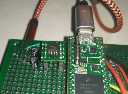
What is this "Audio-master.zip" file? Where do I find it? I found this thread and am having the exact same problem (nothing on pin 2) and so am anxious to fix it, but how?
My pt8211s arrived yesterday so I was anxious to get it working. Since finding this same exact problem I have tried:
removing the 1.8.13 arduino install I was using, deleting all links
Installed 1.8.19 and the teensyduino 1.56
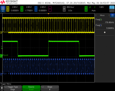
the pt8211 sine test runs when I change AudioObjectpt8211 to AudioObjectpt8211_2 but still nothing on pin 2. Four and three work great, no clock on pin 2.
Please tell me how you fixed this, I'm stuck.
Code:
#include <Audio.h>
#include <Wire.h>
#include <SPI.h>
#include <SD.h>
#include <SerialFlash.h>

// GUItool: begin automatically generated code
AudioSynthWaveform       waveform1;      //xy=110,75
AudioOutputPT8211_2        pt8211_1;          //xy=303,78
AudioConnection          patchCord1(waveform1, 0, pt8211_1, 0);
AudioConnection          patchCord2(waveform1, 0, pt8211_1, 1);
// GUItool: end automatically generated code

void setup() {
  AudioMemory(15);
  waveform1.begin(WAVEFORM_SINE);
  waveform1.frequency(440);
  waveform1.amplitude(0.99);
}

void loop() {
}
Yes, that sounds like the same issue I had. I suspect that you're also seeing a warning, whenever you compile, saying that there are multiple library files named 'Audio.h'. I believe that's because one from Adafruit is automatically installed with the Arduino IDE. Adafruit have their own I2S audio board, so they simply forked the Teensyduino repo on github and changed the pin definitions for DIN, not pin #2.
When you install Teensyduino, it includes the correct Audio.h for the pt8211_2.
I found that including audio_master.zip (from the PJRC repo on github) didn't always solve the problem. So, assuming that you're running Windows here's what does:
1: Open File Explorer and navigate to C:\Program Files (x86)\Arduino\libraries
2: Delete all files named Audio.h within that folder and subfolders
3; Reinstall Teensyduino to include the proper Audio.h
Works for me, anyway. Please let us know whether it solves your problem, as well.
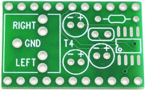
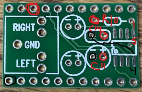
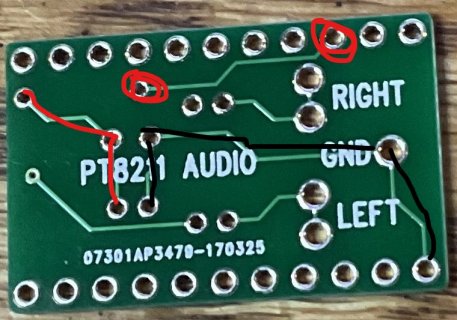
BTW, did you see my approach to modifying the T4 PT8211 breakout board? I used stackable headers (in case I need to replace the PT8211,... again), then cut the pins on the headers to stop the original signals on pins 7, 20, & 21 from reaching those inputs to the PT8211. Then, I rerouted those inputs to pins 2,3, & 4.
Of course, it would be much more convenient to simply have a new T4 PT8211 PCB, with the new pin #s, then standardize it for compatibility with the SGTL5000 I2S shields. Perhaps, someone more clever than I, would like to tackle that someday. JS.
hope this helps. Best of luck with your project.

