Teensy Convolution SDR (Software Defined Radio)

Frank

Just an FYI.

I just now got the program to compile and load. It was complaining about a missing library "SPIN.h". I found those files on the 'net and created the library folder...Voila! The console shows a bunch of warnings and informational stuff, but the program seems to be working. If I open a serial terminal, I can see some timekeeping and other status information coming from the Teensy.

So, it looks like I'm off to the races! I now have to build up a test platform with the Teensy, audio board, display and switches. Hopefully it will become much more interesting and rewarding from here.

Joe
 
Last edited:
Frank

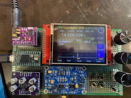
I have the code compiled, uploaded to the Teensy 4 and running with the audio board and display. One thing I notice is that the GUI runs for about 10 seconds at 135.600 MHz, then goes all white. Should I assume this means it crashed because I don't have the Si5351 I2c connected?

Joe
 
@Joe: I do not know, because your setup is unknown to me. For the radio you need: T4, ADC, DAC, Si5351 LO, ILI9341 TFT, encoders, buttons, and a quadrature sampling detector (and RF input lowpass or bandpass filters). If your setup lacks one of those components, it can react weird :). So there is no way for me to answer your question. What do you mean by "the GUI runs" and how and why did you tune to such a weird frequency? BTW, even if you had the Si5351 connected, it can NOT tune the SDR to 135.6MHz. The Si5351 is limited to about 290MHz, thus Rx frequency is limited to 290/4 == 72.5MHz

My suggestion would be to completely build the SDR and then test it. Otherwise you will always be speculating why your setup behaves this or the other way.

One speculation would be that your TFT connection wires have problems with correct soldering or are much too long.

P.S.: Of course -as you probably know- the radio can receive at the third harmonic, so Rx frequency can be as high as 290/4 * 3 == 217.5MHz, but at the expense of an attenuation of 9dB [and all your components in the QSD front end have to be compatible with such high frequencies and you would have to highpass / bandpass filter the RF input to prevent aliasing]
 
Frank

I think you don't understand. I have the Teensy, the PJRC audio board and ILI9341 display running together and executing your latest code. The GUI comes up just fine at a default frequency of 135.600, every time. This is with no other peripherals (encoders, Si5351, etc) connected. I consider this a pretty well-defined hardware configuration, if not the complete configuration. The display runs and looks like your posted photos, but it crashes after about 15 seconds. I'd don't think it's the absence of an I/Q demod; that only results in no audio input. With some other graphics test code, the hardware setup works just fine, so it's this particular app that's crashing. From my experience with some Si5351 libraries, they crash when there's no Si5351 hardware attached, but I hoped you might have anticipated this and intercepted that condition, that's why I asked. It might also be the new model PJRC audio board I'm using, I don't know if you tried that yet.

No problem though; I'll trace through the code and try to catch the conditions could cause a crash and intercept them, then we'll know for sure if/what hardware has to be connected in order for the app to run.

I'll advise when there's more progress to report.
 
@Joe: OK, now I understand, you mean 135.600kHz, not MHz :). Yes, that is the expected behaviour of the SDR code to start with that band and that frequency!

I consider this a pretty well-defined hardware configuration, if not the complete configuration.

No, your configuration is not the complete configuration, it is complete when you attach everything that I listed in my previous post. I did not anticipate using the SDR without attaching all of the necessary components including the local oscillator Si5351, because that simply does not provide any radio function at all.

But if you want to use the code without the Si5351, you can try to comment out the init functions for the Si5351 in the setup. And then you would have to look for all functions in the code using the Si5351 and comment those out. But then (and especially if you did not connect an encoder) the script will do nothing except showing the frequency and display the input noise in the spectrum display.

then we'll know for sure if/what hardware has to be connected in order for the app to run.

I am still not sure what you are talking about, maybe I am on the wrong track, I apologise for that.
The hardware necessary for the Teensy Convolution SDR is very clearly defined (have a look into github for the details), so I do not understand your statement. And clearly, if you do not connect all the necessary hardware, the code (and the radio) will not perform as expected.

Good luck with your progress!
 
Frank

I said my configuration is "well defined", not that it is what you anticipated. I was probing to see if you have any suspicion about what you would expect to happen in that configuration.

I don't like the "shotgun" approach to trouble-shooting, ie; hook everything up and "let 'er rip". I like to break the system down into bite-size pieces as I proceed. My intent is to get a stable system with no peripherals attached, then introduce them one at a time to ensure everything is working or else troubleshoot what doesn't work.

I'll get there, and I'll have a much better understanding of the system when I arrive.
 
Frank

I think I localized the cause of the system crashing some 15 seconds or more after startup when there are no peripherals attached. It seems to be associated with no audio into the ADC, possibly causing a divide-by 0 in the twinpeaks correction code? If I initialize the "twinpeaks_tested" variable to 1 instead of 2, it then runs in this "naked" mode, albeit with no twinpeaks detection/correction. On-screen clock and serial monitor output confirms that it's alive.

Please tell me if you think I'm on the right track.
 
Hi Frank,
Just to let you know that I now have the Teensy Convolution SDR up and running. I have picked up a number of MW stations and a few SW stations. Excellent work, I must say.
I used the Teensy 3.6 with a piggy-back Audio board. I have a few questions if I may;
1. Is there a 'cheatsheet' (simple user manual) to understand the menu options and the key sequences to select the correct menu choices and what is the expected outcomes? As an example, what would bit number mean?
2. As some enhancements, I tried adding an RF Preamp about 18.5 dB gain, this works very well, but should this stage be added or not? What is everyone's thoughts on this?
3. I was thinking of adding a PI-Attenuator of 3/6/9 db switchable. Again, is this something that should be added? or is the internal software based attenuator sufficient? I seen something as the PExxx att in the notes, This I find a bit complex, but, I could add that if necessary (or a solderable DIP/SMD alternative?)
4. Is a RF BPF necessary for each band? How would this be driven?
5. I have added a LM380N amp to the Line out. this works well. What are the recommendations for a separate volume (hardware based ) control?

Some problems I have been facing when I have been 'playing around'.
a. The screen sometimes goes white, not sure what causes this?
b. The sound makes a sharp 'click' at times and it stops momentarily, what causes this?
c. The step size is half of what is displayed, it used to work correctly earlier. Did I make a change somewhere incorrectly? The 1 Hz step is accurate.
d. How do I run the calibrate routine?

I have changed the code to use a 25Mhz XTAL and also my board uses CLK0 so have modified the line
Code:
 define Si_5351_clock  SI5351_CLK0

Sorry if there are too many questions, but I thought I'd get some thoughts in before I start choosing a box.

Many thanks for your time.

/MICUPRE
 
@MICUPRE: great to hear its working for you! Just some short answers to your questions:

1. https://github.com/DD4WH/Teensy-ConvolutionSDR/wiki/Menu , also have a look at the other entries in the WIKI, maybe you find what you are looking for.
2. RF preamp is not generally needed below 20MHZ, IF you have a nice 50 Ohm antenna. If you only have a piece of wire, a preamp does make some kind of sense, but testing this for your specific situation is vital.
3. If you need an attenuator, why not add it to your setup :)
4. Definitely you need about 50 to 60dB of attenuation of your RX frequencys´ third harmonic, eg. to receive properly at 531kHz, you will have to install a lowpass RF filter in the frontend, that has 50-60dB attenuation at 1593kHz --> you probably need elliptic 7-pole lowpass filters for that. Highpass filtering is much less important.
5. Maybe use a pot at the input of the LM380?

a) You seem to have problems with incorrect switches that you set in the software, maybe additionally contact problems with the TFT wires. Provide highres pictures of your hardware setup, so we can see what you built, otherwise we are wildly speculating here . . .
b) you spoiled something in the software or you did not take the latest software version from github. Did you change AudioMemory ?? If yes, be very careful with that!
c) very odd! Seems to me like a severe hardware failure with your Si5351, your Johnson counter OR you spoiled up something very serious in the software
d) ??? there is no calibration routine, search for China Radio International, switch to SAM demodulation and adjust calibration constant and calibration factor in the menu, until frequency is spot-on. Do this for different bands, re-adjust several times and then save those settings to EEPROM. China Radio International is one of the very few radio broadcasters, that are accurate to one Hz in their Transmit frequencies, most other international broadcasters are off, up to 100Hz sometimes, even worse for some Brazilian national radio stations ;-)

My recommendation would be to use a 27MHz TCXO instead of a 25MHz crystal for the Si5351, then your frequency will be super-accurate [However it is quite accurate and temperature stability is high even with crystals like yours].

Good luck with your progress!

Frank DD4WH

Hi Frank,

Thank you for your time and advice on this. I will reinstall the FIRMWARE and give it a go.

Best 73,

/MICUPRE
 
@MICUPRE
............
Softrock should work. Does it have an Si5351 as LO? Then it should be easy to modify the code for the SoftRock.

There were many versions of the SoftRock. Early versions were crystal controlled for the LO. Subsequent versions that were more frequency agile used an Si570 to generate the LO. These also used an ATTiny controller that provided host PC connection to the Si570 via USB, and also handled switching of bandpass filters.
That is where the rub comes in. I don't think it is a practical approach to use a Teensy and its USB port to support the Si570 requirements (I could be wrong, but I have been unable to find the details of the required protocol for the SoftRock to reverse engineer it).
However, I have been looking at the concept of using a SoftRock RxTx (transceiver), Teensy with audio board, Si5351, and ILI9341 to create a basic, compact, stand alone SDR transceiver package that could even be battery operated. To that end, I have been using this concept as a learning platform as I am totally new to microcontrollers, C++, and OOP - even though I have other software development experience in a previous life. I am learning a lot, very quickly.
I have 5 or 6 SoftRocks I can play with and even butcher if need be. I am going to start with an old 2 band (40/30m) transceiver that was crystal controlled and use the Si5351 to make it frequency agile. This much I have already got working for proof of concept. The next step will be to disconnect the front end Si570 and ATTiny on a more recent version, replacing its functionality with the Teensy.
Still a long way to go, and my progress was recently hampered when I had a freak accident and broke my neck. Further development got pretty much halted as I convalesce. I hope to return to it soon. I'd be happy to communicate with anyone with a similar interest.
Tom
 
OFFTOPIC: I would recommend to no longer use the Si570 unless you have a very good reason to do so . . .

The Si570:
* needs way too much power supply current
* is much too expensive
* is much too sensitive to temperature fluctuations (which result in frequency fluctuations)
* has lower phase noise than the Si5351, but I have not seen any convincing data/measurements how that relates to better receive properties compared to using the Si5351 as a LO [the theory is clear, but show it to me with real measurement data! ;-)]

my recommendation would be: in this thread, lets talk about SDR software on the Teensy here, not about hardware . . . that is done by many people in many other places.

All the best 73s,

Frank DD4WH

Yes, I agree, that was off-topic and my apologies. :)

Let's stick to SDR software on the Teensy here.

Best,

/MICUPRE
 
Frank, with all due respect since this is your thread and your development project.....
What is off topic is sometimes a gray or fine line. Sometimes a subject is merely tangential, but still pertinent to the primary thread.
When I look at many software projects, such as your masterful convolution SDR, I also try to think of how that development might be leveraged in other similar uses or projects. You have said yourself that using the SoftRock front end should be a possibility with your software. So any discussion of that possibility cannot ignore the pertinent hardware aspects of that option for the simple reason that it affects the required software.
I did not see that anyone was suggesting the Si570 as a viable alternative, and in fact, in my post I think I clearly indicated that working around it (disconnecting it in the circuit) was a more viable approach.
It might be a good ideas to have a separate thread that is specifically SoftRock oriented and where various different SDR programs for the Teensy could be discussed as options in order leave this thread "pure" for discussion of your project.
Regards, Tom
 
Tom, thanks for your thoughtful comment! When saying OFFTOPIC, I meant that MY comment on the Si570 was offtopic. However, you are right, this is the PJRC TEENSY forum and this thread is on Software Defined Radio (Teensy Convolution SDR). So, my wish would be that intensive discussions on the quadrature sampling detector types, front ends and advantages and disadvantages of certain local oscillator ICs is done elsewhere in other forums and we use the excellent PJRC forum for discussions on the software side of Teensy-based Software Defined Radio.
All the best,
Frank DD4WH
 
Frank,
Agreed!!
To that end, I would be interested in having you do a short summary of the theoretical advantages (as well as any possible disadvantages) of using this approach to SDR, along with your real world observations of how well your implementation reflects those theoretical characteristics. I realize that some observations may be subjective as opposed to rigorously measured, but would be useful none the less!
Thanks, Tom
 
Tom, you are probably aware of these resources already, but at these places I have prepared all the info regarding the Teensy Convolution SDR:

https://github.com/DD4WH/Teensy-ConvolutionSDR/blob/master/Teensy Convolution SDR english.pdf

plus a Wiki explaining some parts in more detail (have a look at the right sidebar if you are looking for specific topics):

https://github.com/DD4WH/Teensy-ConvolutionSDR/wiki

there is also a WIKI for an STM32F7-based SDR running the UHSDR software, for which I have prepared even more topics on how QSD SDRs and specifically how the UHSDR software works in detail:

https://github.com/df8oe/UHSDR/wiki/Topics:-UHSDR:-Theory-of-Operation

In the "Links & ressources" section you will find links to the classic SDR papers / books as well as links to open source code libraries:

https://github.com/DD4WH/Teensy-ConvolutionSDR/wiki/Links-&-Resources

In order to get a quick overview, my recommendation to you would be the following order/priority for reading:

1.) the classic papers by Youngblood 2002/2003
2.) the manual by Whiteley 2011
3.) then you might like to read my description of the Teensy Convolution SDR and
4.) every specific topic in the WIKI that you might be interested in

Have fun with reading! And dont hesitate to ask specific questions on specific topics or specific parts of the software.
However, the best would be to start building an SDR after reading and then ask questions afterwards ;-).

P.S.: As you also might already know, I am not advocating one specific approach to SDR, anyone can build/program anything she/he wants. I am not selling anything. This project and this thread is 100% purely educational (and sometimes fun ;-)).
 
Last edited:
Frank,

I want to thank you for the convolution SDR project. It challenged my hardware and software skills and I just got it working today. We use SDR technology at my company using fast multi-core processors and I wanted to see what could be done with the new M4 processors like the Teensy 4.0. I got the code to compile fine albeit with a handful of warnings. All the modes I have checked so far work great. Have you thought about using one of the UHF tuners like the RT820T which have a single ended IF

73's
Jim WB4HYY DD4WH Convolution SDR by WB4HYY.jpg
 
Hi Jim, your SDR setup looks quite familiar to me ;-). Great that it works and that you find it useful. BTW, the current version does not make full use of the T4 power, it already works great with the T3.6 @ 180MHz ;-). [OK, using synchronous AM demodulation at 256kHz sample rate is only possible with the T4 :)]

Which frontend do you use? Is it Joris PCB? If yes, where did you get it? I would be very interested in information on that.

I have not thought about using UHF tuner chips, but maybe you can advance on that? I have no experience in UHF and the tuners used in those cheap SDR USB dongles.

All the best 73s,

Frank DD4WH

Frank,

The frontend is the one from Joris that Rob Engberts (PA0RWE) sells. With the large 0805 parts it was pretty simple to build and worked first time.

I started a project to use the Rafael R820T tuner chip (the same as in many SDR dongles and the Airspy mini) as a UHF front end but did not finish it. Eric Brombaugh published a nice breakout board for the R820T that you can get on Oshpark.

http://ebrombaugh.studionebula.com/radio/r820t2_breakout/index.html

I intended to add a 5351 local oscillator like the Airspy uses and combine it with the NXP IMXRT MCU (like on Teensy 4.0) to build a multi-channel 900 MHz demodulator. With the proper filter settings it possibly could be used with your design but since its a single IF output you would have to sample at 2x or 4x to yield I/Q data in software. The on board ADC on the IMXRT appears to be fast enough to do this.

Jim
 
Hi
First some not so good news to start off with unfortunately.
I managed to _blow up_ my T3.6 earlier today. I am now considering a replacement, but, before I go off and order it again, I thought I should once again ask for advice here. If the question is not relevant to this thread, please tell me off and let me know where I could ask this elsewhere on the forum.

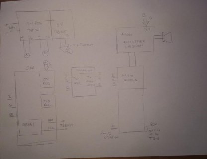
The connection diagram is Teensy3.6-SDR-conns-1.jpg

At first everything switched on as normal, but getting getting sound proved a challenge. Maybe there were a few loose connections so I rechecked those. I then removed the 5V connection to the T3.6 and connected an external powerbank as I was doing earlier during my testing phase. This worked as normal and I was able to listen in to AM signals.

I then switched it off and connected the 5V supply and GND to the first pins of the T3.6. The radio would not work and it produced a hiss. I managed to switch powersupply connections and got it working.

I did some quick checks and found that the SDR board Ground was 1.77 volt higher than the power supply ground. I'm not sure what happened here. As I was trying to solve this. I heard a pop and the display went blank.

During my testing phase I was driving the T3.6 with a separate power supply and I would switch this on after the SDR and the AMP was switched on and things worked. It is only when I integrated all the boards (T3.6) on the 5V supply that things got undone.

How can I prevent this from re-occurring? I was thinking of the T3.5 as this is 5V tolerant. What is a better way of connecting so there are no glitches on switch-on?

Also, the 5V regulator would get very HOT, is there any way to solve this too?

Many thanks for your time.

/MICUPRE
 
Last edited:
@MICUPRE: sorry to hear about your blown-up T3.6 !

Before connecting a new T3.6 to your current setup I would carefully check it. I do not understand fully your connection diagram, however there seem to be some odds:

* audio shield and T3.6 should be solder connected with all pins. Is that the case in your setup? I think the main cause for your problem could be that you did not connect 3V3 Teensy pin with the 3V3 audio shield pin! The 5V pin of the audio shield is not connected to anything, so the audio shield will not be powered correctly, if you connect anything there.
* your ISOLATION block is mysterious to me: what is it? Does your setup have a common GND rail?
* In my opinion, all your GNDs should be connected
* also, I do not know what you mean by "connecting GND to the first pins of the T3.6" --> that sounds as if you connected some GND connection to the 3V3 pin of the T3.6 OR you connected AGND to Vin!? Please be careful: GND and AGND are on different sides / positions of the T3.6 PCB!

Good luck,

Frank DD4WH

P.S.: Using a 5V-tolerant T3.5 will not solve your connection problems
 
@Jim: thanks for your info!

I am not sure if it will be possible to use the R820T tuner. As far as I understand, one would have to sample the IF with at least 20Msps (IF == 10MHz) and then run a sin/cos multiplier inside the software at that speed to produce an analytical (IQ) signal before being able to down-translate the IF by decimation. My impression is that even a T4 would not be able to do this.

73 Frank DD4WH
 
@MICUPRE: sorry to hear about your blown-up T3.6 !

Before connecting a new T3.6 to your current setup I would carefully check it. I do not understand fully your connection diagram, however there seem to be some odds:

* audio shield and T3.6 should be solder connected with all pins. Is that the case in your setup? I think the main cause for your problem could be that you did not connect 3V3 Teensy pin with the 3V3 audio shield pin! The 5V pin of the audio shield is not connected to anything, so the audio shield will not be powered correctly, if you connect anything there.
* your ISOLATION block is mysterious to me: what is it? Does your setup have a common GND rail?
* In my opinion, all your GNDs should be connected
* also, I do not know what you mean by "connecting GND to the first pins of the T3.6" --> that sounds as if you connected some GND connection to the 3V3 pin of the T3.6 OR you connected AGND to Vin!? Please be careful: GND and AGND are on different sides / positions of the T3.6 PCB!

Good luck,

Frank DD4WH

P.S.: Using a 5V-tolerant T3.5 will not solve your connection problems

Thanks Frank for your patience. I had not made a proper diagram and I think I did not explain it quite well either. Let me elaborate a bit.

1. The Audio shield is piggy-backed on the Teensy. All pins are connected from the Audio Shield to the T3.6.

2. The isolation block is a pair of 600R 1:1 transformer to prevent the spurious noise (noise level was very high when I connected the SDR to Audio Shield directly) getting across the audio. One side of a transformer connects to the SDR side (I) and the other side connects to the Line Input of the Audio Shield (L). Similarly, for Q.

3. SDA, SCL and Ground are connected from the T3.6

4. VIN and GND. Looking at this link here https://www.kickstarter.com/projects/paulstoffregen/teensy-35-and-36 , the pins I used were VIN and the GND pin on the direct opposite side of the board.

I hope I explained everything correctly and thank you once again for your time

Regards.

/micupre
 
Back
Top