mjs513
Senior Member+
I have a library based on NXP Quad Encoder SDK driver for the Encoder module but modified to support the Teensy 4.x infrastructure.
NOTE: you will need to incorporate the Update imxrt.h for encoder structure #402 to make use of the library.
There are 4 hardware quadrature encoders available the Teensy 4.0. These are currently supported on FlexIO pins: 0, 1, 2, 3, 4, 5, 7, 30, 31 and 33. The library is available in my GitHub repository: https://github.com/mjs513/Teensy-4.x-Quad-Encoder-Library.
Basic usuage for the T4 is similar to the current Teensy Encoder library.
A similar to example to that on https://www.pjrc.com/teensy/td_libs_Encoder.html is shown below. See SimpleEncoder.ino in the examples folder.
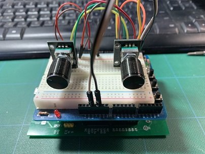
Using two KY-040 Rotary Encoder Module was tested:

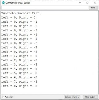
with the following output on the serial monitor:

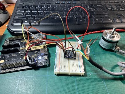
In addition a Rotary Encoder with Different Resolutions (200PPR, Line driver with 5V was used to test the index pin functionality:

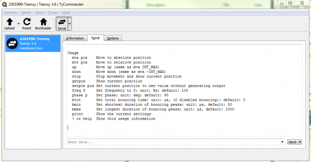
A few examples are included in the library showing its capabilities.
Enjoy. Let me know if you run into any problems.
NOTE: you will need to incorporate the Update imxrt.h for encoder structure #402 to make use of the library.
There are 4 hardware quadrature encoders available the Teensy 4.0. These are currently supported on FlexIO pins: 0, 1, 2, 3, 4, 5, 7, 30, 31 and 33. The library is available in my GitHub repository: https://github.com/mjs513/Teensy-4.x-Quad-Encoder-Library.
Basic usuage for the T4 is similar to the current Teensy Encoder library.
Code:
QuadEncoder myEnc(enc, pin1, pin2);
   enc - encoder object (specify 1, 2, 3 or 4).
   pin1 - phase A
   pin2 - phase b
myEnc.read();
   Returns the accumulated position. This number can be positive or negative.
myEnc.write(newPosition);
   Set the accumulated position to a new number.
A similar to example to that on https://www.pjrc.com/teensy/td_libs_Encoder.html is shown below. See SimpleEncoder.ino in the examples folder.
Code:
//
* http://www.pjrc.com/teensy/td_libs_Encoder.html
*
* This example code is in the public domain.
*/

#include "Quadencoder.h"

// Change these pin numbers to the pins connected to your encoder.
// Allowable encoder pins:
// 0, 1, 2, 3, 4, 5, 7, 30, 31 and 33
// Encoder on channel 1 of 4 available
// Phase A (pin0), PhaseB(pin1),
QuadEncoder knobLeft(1, 0, 1);
// Encoder on channel 2 of 4 available
//Phase A (pin2), PhaseB(pin3), Pullups Req(0)
QuadEncoder knobRight(2, 2, 3);
//   avoid using pins with LEDs attached

void setup() {
 Serial.begin(9600);
 Serial.println("TwoKnobs Encoder Test:");
 /* Initialize Encoder/knobLeft. */
 knobLeft.setInitConfig();
 //Optional filter setup
 //knobLeft.EncConfig.filterCount = 5;
 //knobLeft.EncConfig.filterSamplePeriod = 255;
 knobLeft.init();
 /* Initialize Encoder/knobRight. */
 knobRight.setInitConfig();
 //knobRight.EncConfig.filterCount = 5;
 //knobRight.EncConfig.filterSamplePeriod = 255;
 knobRight.init();
}

long positionLeft  = -999;
long positionRight = -999;

void loop() {
 long newLeft, newRight;
 newLeft = knobLeft.read();
 newRight = knobRight.read();
 if (newLeft != positionLeft || newRight != positionRight) {
   Serial.print("Left = ");
   Serial.print(newLeft);
   Serial.print(", Right = ");
   Serial.print(newRight);
   Serial.println();
   positionLeft = newLeft;
   positionRight = newRight;
 }
 // if a character is sent from the serial monitor,
 // reset both back to zero.
 if (Serial.available()) {
   Serial.read();
   Serial.println("Reset both knobs to zero");
   knobLeft.write(0);
   knobRight.write(0);
 }
}
Using two KY-040 Rotary Encoder Module was tested:

with the following output on the serial monitor:

In addition a Rotary Encoder with Different Resolutions (200PPR, Line driver with 5V was used to test the index pin functionality:

A few examples are included in the library showing its capabilities.
Enjoy. Let me know if you run into any problems.
Last edited:


