First of all thank you for your answers.
I will use the square 240x240 LCD display.
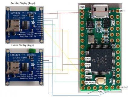
The first thing I tried to do was to draw the wiring between the two TFT's and the teensy by following the pin design from Chris's code.
#elif defined USE_ST7789
ST7789_Config eyeInfo[] = {
// CS DC MOSI SCK RST ROT MIRROR USE_FB ASYNC
{ -1, 2, 26, 27, 3, 0, true, true, true}, // Left display
{ -1, 9, 11, 13, 8, 0, false, true, true}, // Right display
};
Unfortunately I didn't understand where the CS connections from the TFT's are connected to the teensy.
Or does the "-1" in the code have a different meaning and the wiring is already finished - as shown above?
In the official pin-out, pin 10 is CS.
I have for now put both CS connections on pin 10 and hope this is correct (dashed line)?
Another CS port seams to be on the back of the teensy 4.0 (pin 36).
Each display's CS pin should connect to a separate pin, and then in config.h you edit the code to list that pin. If the device doesn't have a CS pin, then you would put -1 for the CS pin. Some of the square 240x240 displays don't have CS pins.
The role of the CS pin is to enable the device when you have multiple devices on a SPI bus. I.e. on a shared bus, you have the 3 standard SPI pins that all devices use (MOSI, MISO, and SCK), and the CS pin is unique for each device. Essentially the displays are like an old fashioned party line in rural areas, where everybody is on the same line, and the CS pin says who the communications are meant for.
If you are curious, D/C tells the display whether the data being sent out is data or SPI command, and RST resets the display.
My personal setup is:
- Display #1, MOSI = 26, SCK = 27, CS = 0, D/C = 24, RST = 25
- Display #2, MOSI = 11, SCK = 13, CS = 22, D/C = 9, RST = 10
In looking at this, I should have reversed the order of the displays, so if you have only one eye, it uses the pins you can get to easily on the Teensy 4.0. Maybe I will reverse now that I looked at the code again.
For Teensy 4.x processors, it doesn't matter what digital pin you use for CS. The CS, D/C, and RST pins have to be unique for each device.
For Teensy 3.x processors using the 128x128 displays there several special CS pins that if you select the appropriate pin for CS and D/C it will allow you to speed up the display, and you use the same MOSI/SCK for both displays.
If you have a Teensy 3.x, this post highlights these special CS and D/C pins:
https://forum.pjrc.com/threads/33014-SPI-Chip-Selects-(Teensy-3-1-vs-3-2)?p=96072#post96072. There are 9 special CS pins, but you can only pick certain combinations.
The optimization requires both CS and D/C to have these special SPI pins. On the Teensy 4.0, there is only one special CS pin (10) for the first SPI bus, and one special CS pin (0) for the second SPI display. The Teensy 4.1 added 2 more special pins for the first SPI bus (36, 37) and 1 more special pin for the second SPI bus (38).
As far as I know, none of the libraries use these special pins in the Teensy 4.x. In the original Uncanny Eyes code, they only used the libraries to set up the displays, and the Uncanny Eyes code talked directly to the displays. In the newer code for the Teensy 4.x, all of the special code that talked directly to the device was removed, and the code now uses the libraries to talk to the device. The libraries have some options to speed things up such as using DMA and secondary frame buffers.
I tend to set up Teensys like tinker toys (tm), in that I try to set up pin assignments, so that I can mix and match different things. I also setup a common wiring for displays, so that I can make a cable from the display that has the pins laid out in a standard configuration, so that I can easily switch between 128x128 OLED, 128x128 TFT, 240x240 square, and 240x240 round displays, even though the order of the pins on each display is different.
The support for the Sparkfun person sensor sounds really cool.
Is there a video on how this works or is it still in the development stage?
Chris added the code just before dropping off the list. It should be earlier in this thread.
Also there is this page:
https://www.hackster.io/useful-sensors/projects on projects people have done with the sensors.
A picture of how the sensor is connected to the teensy would be helpful.
It is a standard I2C sensor, i.e. you hook up 3.3v, ground, the SCL pin to pin 19, and the SDA pin to pin 18.
I my opinion it would be even better if the head turned in the direction where a face was recognized, controlled by a servo.
Is this possible or has anyone already tried it?
Yep. There is this code for Arduinos from several years ago:
https://www.instructables.com/Arduino-Animatronic-Eyes/.
There is also this site that offers Hardware, Electronics, Supplies, Custom Engineering and Technical Assistance for the
Animatronic, Robotic, Electronic Arts, Entertainment Engineer, for theHobbyist and Professional:
http://www.bpesolutions.com/bpemodel.html.
Note, I just saved those links when I noticed them, but I haven't looked at them.
Does the alternation between eyes occur automatically and can I switch it off?
I would only need one eye style for my current project.
Greetings
Peer
Its in the code in config.h. Each eye is a separate .h file. You would just reduce the list to the eye that you wanted, and change the count of the number of eyes to 1. If desired, you could eliminate the code that selects the new eye.
In the code that Chris started from on Adafruit, there is support for only one eye, and it is not compiled into the code, but instead it is read from flash memory at boot time. This way you could easily replace the eye you wanted to use without having to recompile it. For example, on the Adafruit Monster M4SK product (basically 2 displays set up for goggles/eyeglasses), there are 3 buttons on the M4SK. The flash memory can hold 4 eyes, and you select which eye you want when the M4SK is turned on, either by pressing no buttons, or pressing one of the 3 buttons on the M4SK.
Here is the Adafruit learning guide for the Monster M4SK:
https://learn.adafruit.com/adafruit-monster-m4sk-eyes.
I've always wanted to restore that functionality, using either the SD card in the Teensy 4.1 or using flash memory and MTP so things can be done via USB like you could do with the Monster M4SK. Note, the M4SK is memory limited, and it can only hold one eye at a time.
The Teensy 4.0 is less memory limited, and I found I could hold 8 eyes in it (cat, demon, dragon, hazel, hypnoRed, skull, snake, and toonstripe), while the Teensy 4.1 has more memory, and I could fit all 23 eyes. I could also fit 5 small RAW sound files before running out of program memory.

 )
)