Accessing bottom pads on T3.6

Status
Not open for further replies.

Bob Larkin

Well-known member
I've hunted but not found the answer. I need just a few more digital pins from the bottom pads of the T3.6. Frank B's Connector Board 3 for T3.2 would seem to do the job fine, if it fit. https://pcbs.io/share/46718

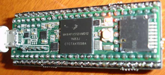
Is there a similar board, for the T3.6, that would connect to the pins under the SD card?

To get started, it appears that the 3.2 Connector Board could be used under the 3.6, bringing out pins 41, 43, 44, 45, 46, 47, 48, 49, 50 and 52. It would also need some insulating tape over some pins to prevent shorts. Has anybody done this?

Thanks, Bob
 
There are the talldog boards:

And this classic post from Jimmayhaug originally for 3.0 or 3.1 of one way to attach pins to the bottom if you don't have a PCB:

I imagine a regular protoboard under the 3.6/3.5 with pogo pins may work if you wanted to make the Teensy removable using male pins for the outside pins fitting into normal female headers.

Note, the 5 inner pins on the 3.6 that add the USB host (and 2 extra analog input pins on the 3.5) are not aligned on a 0.1" boundary.
 
Last edited:
Thanks, Michael. I was unaware of the Talldog boards. Those look interesting for prototyping in general. They are a bit more than I need now. I am laying out a board using the T3.6 as a component, and don't want to grow the size any more than necessary.

I did a conceptual layout of a new T3.6 board like Frank B's and it looks like I could pick up all 14 pads on the SD card end. This would require running a couple of traces on the outside of the main pin row (one on each side), so the extension board would be slightly wider than the Teensy 0.7 inch. If I stayed to 14 pins on the extension part of the board, like Frank did with the 3.2 board, it would meet my needs. By going to a third row it looks like it would be possible to pick up Reset and VBat. Is that of value to anyone? That same extra row could include a ground or two that never hurts to have. I think all those traces can be run without needing more than two traces between pins.
 
Yes I would be interested, particularly if is castellated like Frank's board. One suggestion would be to see if you can label the pins on the silk screen, so that you don't have to resort to a web site to find which hole corresponds to which pin. I believe Frank has since updated his design to indicate the pins.
 
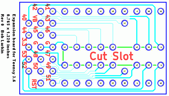
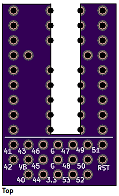
Here is a cut at a simple board in the spirit of Frank's:
T36ExtBrd_H_Rev0.gif
This is close to being ready to go to OSH Park. It will need a hand cut slot, I think. I don't think this is hard to do, as the FR4 saws and sands with minimal effort. Comments are welcome. I am challenged for viewing things upside down, but I think it is right!

This board only deals with the pins on the SD card end. Also, as it is, it blocks bottom access to the Program, Ground and 3.3 header pins in the middle. Top access remains.

Thanks, Kurt for the referenced thread with your expansion card. There are lots of good ideas on this thought, depending on what it is for. I had not seen that thread and it had much good reading.
 
I meant to mention that, as Frank did, I put the traces all on the bottom. The view shown is from the top, though. And the pin numbers are, of course, on the top silk. The slot outline for cutting is on the bottom silk.
 
If I remember correctly, you can put in a rectangle into the Board outline gerber file for the cut out and OSHPark can in many cases do the cutout for your.

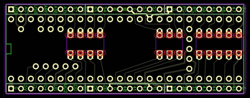
Example of the T3.6 I was playing with earlier.
T36_cast.jpg
 
My concern was cutting through the through holes. OSH Park indicates, "No copper present beneath the cutout" that might indicate a problem. Have you or others used slots with routing along through the holes? At $5 the easiest thing might be to submit a board...
 
Indeed Frank's board from OSH ( and other's - boards and PCB houses ) removes the PCB material before shipping. Right through the plated hole that survives intact, sometimes with a minor fold/burr of the plating wiped over depending on the cut speed and bit sharpness.
 
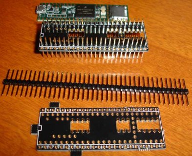
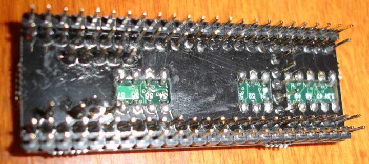
Yep - probably easyiest thing to do is do a trial run and then see if you need to do any slight tweaks to your design... I know I posted some of this earlier probably in the K66 beta thread or maybe the T3.5 thread, but I did assemble one back then...
T3.6-castellated-parts.jpg

T3.5-castellated-bottom.jpg

T3.5-castellated-top.jpg

It has been awhile since I played with it. I have built a couple of the Tall Dog boards as well
 
I ordered three boards. These are like the ones above, but less errors!
T36ExtOrder.gif
I hope there are no hiccups in cutting through the holes.

As soon as these are received and checked out, I will make them public on OSH Park.
 
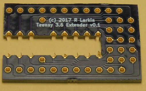
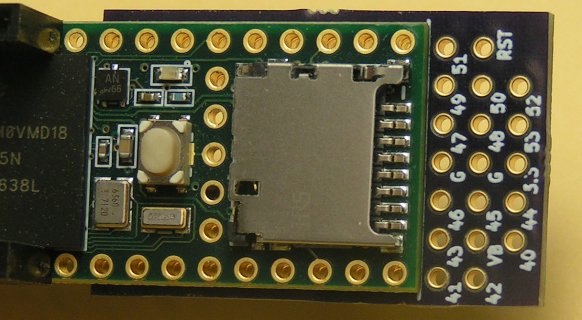
The boards came from OSH Park. They cut the slot, as specified. They will work, but there are a couple of qualifiers. When their router cuts through the middle of a hole, one side is cut cleanly. The other side has a small piece of copper hanging away from the cut. As a hobbyist issue, this can be dealt with by hand cutting the pieces off. Alternatively, and what I did, is to use a dental probe to bend the piece to open the "half hole" and solder everything to the T3.6 board bottom. Here is what the board looks like, with the pieces bent out:
T36Ext674.jpg
This soldered fine to the T3.6:
T36Ext669.jpg
And the markings worked out fine:
T36Ext672.jpg

Looking at the board under a microscope showed that a small part of the metal was sometimes pulled away from the board material, inside the half-hole. The metal was intact, but I would suggest inspecting for this, in case a break had occurred. One cannot fault the board maker, as we are asking for them to cut the slot with metal breakout, something that is not recommended.

With any of these extenders, there is an issue with making sure that the through-holes along the T3.6 edge are properly connected. There are several ways, and what I did was to put individual pins through that could be soldered on both the extender board as well as on the Teensy. I used a socket to align the pins with other Teensy pins.

Unless some issue is reported in the next day or so, I'll make the OSH Park board public, and leave a link here. Bob
 
That looks good. I'd order some. As noted above I saw similar burrs wiped on FrankB's board from OSH - I had some of those made at PCBS.io and their bit cut them cleaner. Onehorse ships some of his boards cut like that and they are not that extreme - not sure who made them. Maybe a dull bit batch?

Why is the midboard GND pin through hole not opened up to pass a pin? That could prevent it from mounting usefully if mounted to another PCB that requires it. Nice job fitting the silkscreen labels by the pins - would be gratuitously awesome to have them on the bottom for those with flipped board dyslexia.
 
That looks great. I should have hinted at outboard silkscreen on the Teensy pins too.

<and OSH showed me the shared board and $4.70 for 3>
 
Okay, I'll settle for that merely awesome version :) - Thanks. Not that I know I need it - but I have collected a few OSH cart things so I'll use this as the reason to finish the order.
 
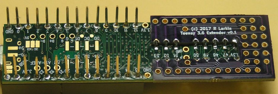
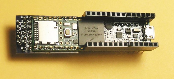
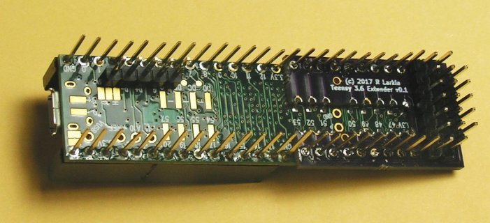
Nothing new, but here are a couple of pictures of the installed extender on the T3.6.
P683T3-6Extended2.jpgP685T3-6Extended1.jpg
These are setup to allow the Teensy to plug into a main board and the audio codec board to plug from above the Teensy. Including the USB Host pins, I think it is 72 pins total. I wondered if I could get all those pins to line up well enough to get into their sockets, but that went well. I started from one end, and in a couple of cases needed to push a pin slightly. If you are trying to do this with a proto-board type of socket, install the USB pins last, as they are not on 0.1-inch centers.

What seemed to be helpful was to have the pins in a socket when they were soldered to the T3-6 or the extender board.

I'm going to use this in a control/DSP box for the DD4WH and DSP-10 radios, which I am now working on.

Bob
 
Status
Not open for further replies.
Back
Top