Teensy 4.x H/W Quadrature Encoder Library

I want to use the QuadEncoder + Interrupts on PinA and PinB. It seems that switsching the Pins (2 and 3) with the XBAR to the encoder disabled the interrupts and vice versa, attaching interrupts to the Pins, disables the QuadEncoder. The later blocks the former.

Any idea to habe Filtering of the QuadEncoder and Interrupt response on the signal transition (without applying the signal to two Pins)?

Best regards

Edmund

Not really sure what you are asking. But if the question is if you can attach an interrupt to same pins as you are using while you are using the encoder library the answer is no. The library uses it own set of interrupts to determine when the triggers are set.

The library provides filtering capabilities as illustrated in the QuadEncoder Example.

You might want to check this thread out on how to set up an interrupt based on a compare value: QuadEncoder Compare Interrupt
 
OK, thank you. As far as I could see that is not described on the teensy homepage or in your library, maybe it should be added.

Anyhow the library works very well for me and the filter function makes it very stable for high speeds.
 
is it possible to use 6 quadrative encoders on a T4.1 ?

how does it work ? does the t4.1 have 2 processors and one of them is dedicated to counting pulses ?
 
is it possible to use 6 quadrative encoders on a T4.1 ?

how does it work ? does the t4.1 have 2 processors and one of them is dedicated to counting pulses ?

You can get the library and its examples, etc. from the github link below. The T4.1 has only one CPU, but it also has many peripherals, including several types of timer that can count pulses or measure periods, and one particular type of timer called QuadTimer that can do quadrature up/down counting on the basis of A and B signals from an encoder. It looks like the library supports only 4 instances, but I'm not sure if that is the absolute limit. Still, if you use this library for 4 of your 6 encoders, that should help a lot. Use QuadEncoder for whichever encoders have the highest resolution and speed, and use the Encoder library for the slower ones. There is a link to the T4.1 processor reference manual at the bottom of the T4.1 product page at pjrc.com. I highly recommend at least looking through the table of contents to get a sense of the capabilities, and then read the section on QuadTimer.

https://github.com/mjs513/Teensy-4.x-Quad-Encoder-Library
 
Hi Joe,

thank you for the prompt reply - i like your idea to improve performance using 4 of the 6 encoders with this library

i will do some reading :)
 
is it possible to use 6 quadrative encoders on a T4.1 ?

how does it work ? does the t4.1 have 2 processors and one of them is dedicated to counting pulses ?

joepasquariello said:
It looks like the library supports only 4 instances, but I'm not sure if that is the absolute limit.
The IMXRT1062 has a only 4 hard wired quad encoders built in so the library was built that limit. So yes its a hard limit on the library
 
Hi mjs513

I'm having a curious issue with this library when definint phase A as pin1 and phase B as pin 3 on a Teensy 4.1.

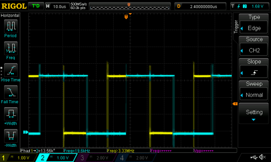
The signal and phase offset looks good on the scope (there is overshoot and a little ringing) but it only randomly counts +- a count occasionaly.

DS1Z_QuickPrint19.png

If I define pin 2 to be phase A the whole lot works fine.

I have changed the teensy 4.1 to make sure it is not a hardware issue and the problem occurs with both.

I note that UART1 default Tx is also Pin1. I am not using this UART but I am wondering if I need to disable that mapping somewhere in case that is keeping pin1 defined as an output somehow?
 
Hi mjs513

I'm having a curious issue with this library when definint phase A as pin1 and phase B as pin 3 on a Teensy 4.1.

The signal and phase offset looks good on the scope (there is overshoot and a little ringing) but it only randomly counts +- a count occasionaly.

View attachment 30800

If I define pin 2 to be phase A the whole lot works fine.

I have changed the teensy 4.1 to make sure it is not a hardware issue and the problem occurs with both.

I note that UART1 default Tx is also Pin1. I am not using this UART but I am wondering if I need to disable that mapping somewhere in case that is keeping pin1 defined as an output somehow?

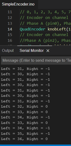
That really is strange. I just did a simple setup with a KY-040 rotatary encoder attached to pins 1 and 3 to try and duplicate. I then ran the simple encoder example and it did not have a problem working:
Capture.PNG

You could try telling it to use pullups:
Code:
QuadEncoder knobLeft(1, 1, 3,1);
to see if it helps.

Also could be something in the sketch or your hardware? Does it work with Paul's Encoder library?
 
The Encoder example available from the Arduino list works just fine, is this using your library?

If so, there is obviously something in my project screwing things up.... will need to dig around and look for anything playing with pin 1...
 
The Encoder example available from the Arduino list works just fine, is this using your library?

If so, there is obviously something in my project screwing things up.... will need to dig around and look for anything playing with pin 1...

The example above is using the QuadEncoder Library.
 
@mjs513 is there a way to detect speed in the form of RPM?
I am using an optical encoder on a Pioneer CDJ1000 jog wheel using the following circuit:
cdj_encoder_circuit.jpg

(do I need pullup resistors on JOG1 & JOG2 lines?)
(Powering with 3.3v)

I know the encoder has 3600 pulses per rotation.
I need to know what the speed is, what the direction of rotation is and the pulse count

Would appreciate some help with it
 
(do I need pullup resistors on JOG1 & JOG2 lines?)
(Powering with 3.3v)

I know the encoder has 3600 pulses per rotation.
I need to know what the speed is, what the direction of rotation is and the pulse count

Would appreciate some help with it
Havent tested alot of encoders - really only used this one for testing:
1719961547477.png


Dont remember using pullups - level shifter since it was 5v device. But you can specify PU in the constructor:
Code:
QuadEncoder myEnc1(1, 0, 1, 0);  // Encoder on channel 1 of 4 available
                                 // Phase A (pin0), PhaseB(pin1), Pullups Req(0)

Direction of rotation and pulse count come directly out of the library but RPM no. Take a look at the examples +/- sign of the counter will give you direction. Take a look at the examples and the Encoder thread - there is a ton of info on it


You would have to count pulses and divide by time to get the RPM. Think this was asked before someplace on the forum.
 
How are the pulses/steps counted?
I was told from someone who reveres engineered the CDJ1000 that a full rotation of the jog wheel should be 3600 pulses, yet using the example code in the library I am getting roughly 13100 pulses/counts

What is the best way I can measure this? Perhaps just a simple sketch with an interrupt on a digital pin that will increment a count variable and read out after a full wheel rotation?
Interesting is the fact that if you divide 13100 counts/4 you get 3275 counts which is pretty close to your 3600 pulses per revolution which is kind of odd.

You could try using the standard encoder library as a comparison. Its part of teensyduino install.
 
@Rezo @mjs513 it has been a long time since I have done anything with encoders. I used them on some Rovers back a long time ago.
And during the later time of that I used a RoboClaw (BasicMicro) handle the encoders. Please pardon in advance my not too concise writing below.

Earlier when I was doing it manually (either in basic on a BasicMicro processor, or later Atmega328)
How to detect direction. As @mjs513 mentioned the library does it for you. There are several webpages out there that give some basic
understanding on how this works, like:

RPM: as mentioned, you capture how many encoder events that happen over some specific period of time, and then do the math,
that converts to RPM: (encoder count)/(counts per revolution) = revolutions ...

Measuring counts per revolution. As you mentioned, I would maybe try to get the count of encoder events that happen over some number of revolutions. For example, like 10 revolutions. And then divide by 10. For me this sometimes helped me when I was doing it manually, as if I end and not 100% accurate on start and stop location, doing multiple revolutions helped minimize the impact of this.

As for expected counts coming out of a motor, lets say that is installed on a rover. It may depend on how the encoder in connected.
I have had some where something is connected to the actual wheel being driven and an optical encoder that works off of that.
So if you have something like 100 marks on the wheel you would get the count of 100 per revolution...

However others like:
with:

This encoder mounts to the rear of the motor, which runs at the speed of the actual motor, but the motor here
has something like a 30 to 1 reduction built in. For every revolution of your wheel, you would receive about 3000 cycles.

And as for reading being about 4 times to high, As mentioned in the Sparkfun link above as well as the Lynxmotion encoder, there are about 4 counts per cycle... Which may be what you are counting here.
1721248671696.png


Sorry again if this is complete incoherent. :D
 
How are the pulses/steps counted?
I was told from someone who reveres engineered the CDJ1000 that a full rotation of the jog wheel should be 3600 pulses, yet using the example code in the library I am getting roughly 13100 pulses/counts

What is the best way I can measure this? Perhaps just a simple sketch with an interrupt on a digital pin that will increment a count variable and read out after a full wheel rotation?
The root of the word quadrature is "quad" or "four". The idea is you have two square waves (A and B) with 90-deg phase offset, and by counting the rising and falling edge of both A and B you get 4x the resolution, and by keeping track of the order the edges occur, you can determine the direction of rotation. With a 3600-PPR encoder, there will be 3600 full periods of both A and B in one rev, and the total number of rising/falling edges is 3600 x 4 = 14400. If you want to count edges using interrupts, you must interrupt on both edges of both signals to get the correct total, so even at 1 rev/sec (60 rpm) you will have 14400 interrupts/sec, and at 10 rev/sec (600 rpm), you will have 144000 interrupts/sec. It pretty quickly chews up your processing capability and makes it impossible to do anything else. That's why you should use the QuadEncoder library, which does the counting in hardware, and not the Encoder library, which does the counting in software.
 
@KurtE & @joepasquariello

Was kind of hinting at that but probably should have made it clearer.

If you go back in this thread you are going to see a EncSim sketch. In the sketch it specifically states:

Code:
uint32_t ppr = 4 * 3600;            // pulses per rev (*4 for quadrature)

for quadrature you have to multiply your ppr by 4 as Joe started.

As a quick test 4*3600 = 14400. But it your data is showing a few skipped. Runing the following sketch with ppr = 4*3600 and just 1 rpm gives me the following:

Code:
pplication TachSim0 Jul 17 2024 17:55:37
ppr = 14400   rpm =    1.0   frq =    960.0
Current position value1: 14400
Position differential value1: 1
Position HOLD revolution value1: 0

Current position value1: 14400
Position differential value1: 1
Position HOLD revolution value1: 0

Current position value1: 14400
Position differential value1: 1
Position HOLD revolution value1: 0

Current position value1: 14400
Position differential value1: 1
Position HOLD revolution value1: 0


Heres the sketch:

Code:
#include "EncSim.h"
#include <SerialCommand.h>

EncSim tachsim( 0, 1 );    // pins 0=A, 1=B, 2=M

SerialCommand sCmd;        // SerialCommand object

uint32_t ppr = 4 * 3600;            // pulses per rev (*4 for quadrature)
float    rpm = 1;            // rpm = (60*frq)/(ppr*4)
float    frq = (ppr*4)*(fabs(rpm)/60);    // keep this relationship
bool     update = true;            // update = true to trigger one print

void LED_on();
void LED_off();
void rpmCommand();
void pprCommand();
void frqCommand();
void default_fn( const char *command );

#include "QuadEncoder.h"
uint32_t mCurPosValue;
uint32_t old_position = 0;
uint32_t mCurPosValue1;
uint32_t old_position1 = 0;
QuadEncoder myEnc1(1, 2, 3, 0);  // Encoder on channel 1 of 4 available
                                 // Phase A (pin0), PhaseB(pin1), Pullups Req(0)
                                
void setup()
{
  myEnc1.setInitConfig();  //
  myEnc1.init();

  pinMode( LED_BUILTIN, OUTPUT );    // Configure the onboard LED for output
  digitalWrite( LED_BUILTIN, LOW );    // default to LED off

  // Setup callbacks for SerialCommand commands
  sCmd.addCommand( "on",  LED_on );    // Turns LED on
  sCmd.addCommand( "off", LED_off );    // Turns LED off
  sCmd.addCommand( "rpm", rpmCommand );    // rpm followed by new rpm value
  sCmd.addCommand( "ppr", pprCommand );    // ppr followed by new ppr value
  sCmd.addCommand( "frq", frqCommand );    // frq followed by new ppr value
  sCmd.setDefaultHandler( default_fn );    // Handler for command that isn't matched  (says "What?")

  Serial.begin( 115200 );
  delay( 1000 );
  Serial.printf( "Application TachSim0 %s %s\n", __DATE__, __TIME__ );

  tachsim.begin();                // begin()
  tachsim                    // CONFIGURATION
  .setPhase( 90 )                // normal 90 deg phase shift
  .setTotalBounceDuration( 0 )            // no bouncing
  .setPeriod( ppr*4 )                // marker every ppr*4 A/B pulses
  .setFrequency( frq );                // frequency = f(ppr,rpm)

  tachsim.setContinousMode( true );        // don't stop at target
  tachsim.moveRelAsync( rpm >= 0.0 ? +1 : -1 );    // +/- direction
}

void loop()
{
  sCmd.readSerial();
  if (update == true) {
    Serial.printf( "ppr = %4lu   rpm = %6.1f   frq = %8.1f\n", ppr, rpm, frq );
    update = false;
  }

  mCurPosValue = myEnc1.read();
  if(mCurPosValue != old_position){
    /* Read the position values. */
    if(mCurPosValue == ppr) {
      Serial.printf("Current position value1: %ld\r\n", mCurPosValue);
      Serial.printf("Position differential value1: %d\r\n", (int16_t)myEnc1.getHoldDifference());
      Serial.printf("Position HOLD revolution value1: %d\r\n", myEnc1.getHoldRevolution());
      Serial.println();
    }
  }

  old_position = mCurPosValue;
  if(old_position == ppr) myEnc1.write(0);


}

void LED_on() { digitalWrite( LED_BUILTIN, HIGH ); }
void LED_off() { digitalWrite( LED_BUILTIN, LOW ); }

void rpmCommand()
{
  char *arg = sCmd.next();
  if (arg == NULL) {
    Serial.println( "No arguments" );
  }
  else {
    rpm = atoi(arg);                // char* to integer
    frq = (ppr*4)*(fabs(rpm)/60);        // compute new frequency
    tachsim.moveRelAsync( rpm >= 0 ? +1 : -1);    // set direction = f(rpm)
    tachsim.setFrequency( frq );        // set frequency
  }
  update = true;
}

void pprCommand()
{
  char *arg = sCmd.next();
  if (arg == NULL) {
    Serial.println( "No arguments" );
  }
  else {
    int temp = atoi(arg);        // char* to integer
    if (temp > 0) {            // if valid ppr
      ppr = temp;            //   set ppr
      frq = (ppr*4)*(fabs(rpm)/60);    //   compute new frequency
      tachsim.setPeriod( ppr*4 );    //   marker every ppr pulses
      tachsim.setFrequency( frq );    //   set frequency
    }
  }
  update = true;
}

void frqCommand()
{
  char *arg = sCmd.next();
  if (arg == NULL) {
    Serial.println( "No arguments" );
  }
  else {
    frq = (float)atoi(arg);        // char* to integer
    rpm = (60*frq)/(ppr*4);        // back-calc rpm
    tachsim.setFrequency( frq );    // set frequency
  }
  update = true;
}

// This gets set as the default handler, and gets called when no other command matches.
void default_fn( const char *command )
{
  Serial.println( "What?" );
}
 
Coming back to this now that I know exactly how to count the "speed" of the encoder; I need to count the time passed between each pulse on Phase A

Now, I've done this using a simple IRQ method as the standard encoder lib would use
I store the value in an uint16_t that starts with a max value of 65535uS - any interval higher than 65535uS will be set as 65535
So the faster the encoder is spinning, the lower the value will be - eg less time between Phase A pulses.

Question is, can I do something similar with the HW on the T4 QuadEncoder lib?
Can I add a custom IRQ to trigger each time a pulse is detected to update my "Speed" value?
 
There are two ways to measure speed using an encoder. One is to count pulses over a known time period (pulse counting). The other is to measure the time for a known amount of rotation (period measurement). The choice of which to use can depend on your encoder and the requirements of your application. You are talking about the second method, and library FreqMeasureMulti will do this for you. It uses the input capture feature of channels of FlexPWM and QuadTimer timers. Each period measurement is captured in hardware and the ISR within the library writes the delta timer value (period) to a queue. Your code can check for data with available(), then get a value with read() and do your speed calculation. You should look at the library examples. It's very easy to use and works well. The main pitfall is if you have a high-PPR encoder and a high rotational speed, FreqMeasureMulti can lead to high interrupt rates. That's a situation where you might use pulse counting.

If you have encoder signals A/B going to pins 0/1, you can use QuadEncoder to do pulse counting, and you can also connect the A signal to pin 2 and use FreqMeasureMulti to do period measurement.
 
@joepasquariello thats for the detailed response!

I specifically need the time delta above, so I will use the quad encoder HW to detect if there is rotation, and what the direction of rotation is, and I’ll use an interrupt on pin 2 to count time between pulses.

Im using a TMM as a secondary MCU to do all the analog data acquisition, and another TMM as a master doing audio and main LCD.
 
What is a TMM?

Just FYI, a long time I made a modification to my own copy of FreqMeasureMulti to allow the time measurement to be made over a specified number of periods (up to 127) rather than always measuring just one period. This can reduce the interrupt rate and provide better resolution when the pulse frequency is very high. Let us know if this would be useful for you and I'll try to resurrect it.
 
What is a TMM?
Sorry, seems Mike answered that for me

Just FYI, a long time I made a modification to my own copy of FreqMeasureMulti to allow the time measurement to be made over a specified number of periods (up to 127) rather than always measuring just one period. This can reduce the interrupt rate and provide better resolution when the pulse frequency is very high. Let us know if this would be useful for you and I'll try to resurrect it.
Appreciate the offer! For now I will just have a go with the interrupt on pin #2 with the signal from Phase A
When doing this bridge between pin 0 and pin 2, should I add in any passive components, such as a diode or something to make sure there is no noise or reverse voltage going back to pin 0? or is this overkill?
 
Back
Top