Latest activity
-
Ttheboot900 replied to the thread Diy teensy sdram solder yourself.I ordered one of dogbones boards and got it stable at 221mhz with a 10pf capacitor. However I think the routing for the sdram for that board was a replica of the imxrt1060 dev board. There routing pattern would be professional. I can get my...
-
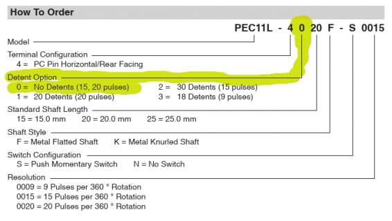
 PaulStoffregen replied to the thread Teensy 4.1 Encoder library no interrupts incrementing by 4 w/ Bourn rotary encoders.If you buy the version without detents so it turns smoothly, you'll see the software really is working as it should and you'll get 60 or 80 counts (depending on which resolution you buy) per 360 degree turn. 4 counts per pulse is the correct...
 -
-
PaulStoffregen replied to the thread Teensy 4.1 Encoder library no interrupts incrementing by 4 w/ Bourn rotary encoders.It's a well know hardware feature, or "issue" depending on your point of view. The hardware has "click" detents on every full cycle of the quadrature waveform. Since they're quadrature (quad = four) you get 4 changes counted, because the...
-
 defragster replied to the thread Diy teensy sdram solder yourself.221 unstable ... Not surprising. Others may have though not here on the uniform set of @Dogbone06 boards IIRC. So pushing the 166 MHz part so far seems safe - but beyond the common working <210? it may depend on the PCB build and part? Testing...
 -
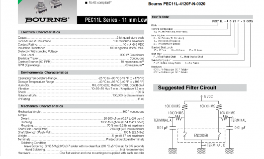
Dd33k posted the thread Teensy 4.1 Encoder library no interrupts incrementing by 4 w/ Bourn rotary encoders in Technical Support & Questions.Hello, I am using some Bourns PEC11L-4120FN0020 rotary encoders as per the recommended schematic in the data sheet connected to a Teensy 4.1 using the PJRC encoder library with no interrupts. The problem I am facing is that the encoders will...
-
-
SStewieman01 replied to the thread Custom Teensy 4.1 Ethernet DHCP Troubleshooting.Is there any specific tool that i could use to determine if packets are being sent? if i assemble a second board could i plug them into each other and read the received packets?
-
defragster replied to the thread ST7796 Teensyduino support.same here. Odd thing is that swapping display for tutorial 3_03 led to broken audio not present with the older smaller ILI display even at the same 'drawn' resolution. SPI used for display is not used for the SDIO file reading - though it is...
-
Pprocoderer reacted to PaulStoffregen's post in the thread UART Communication Issue Between Two Devices (Teensy 4.0 and MSPM0) with
 Like.
Please understand we're blind guessing here. We can only see what you've shown us, which so far is almost nothing. I tried to answer your question whether we've seen this before. But keep in mind I really can't see almost anything right now...
Like.
Please understand we're blind guessing here. We can only see what you've shown us, which so far is almost nothing. I tried to answer your question whether we've seen this before. But keep in mind I really can't see almost anything right now... -
PaulStoffregen replied to the thread UART Communication Issue Between Two Devices (Teensy 4.0 and MSPM0).Please understand we're blind guessing here. We can only see what you've shown us, which so far is almost nothing. I tried to answer your question whether we've seen this before. But keep in mind I really can't see almost anything right now...
-
Pprocoderer reacted to PaulStoffregen's post in the thread UART Communication Issue Between Two Devices (Teensy 4.0 and MSPM0) with Like.
To explain just a bit further, the unable to sync on 100% bandwidth problem has every byte corrupted at the receiver, but they all do arrive at the correct pace. It only happens if the transmitter is already in the middle sending when the...
-
Pprocoderer replied to the thread UART Communication Issue Between Two Devices (Teensy 4.0 and MSPM0).To clarify, most data doesn't arrive correctly. None of the data arrives correctly (unless by coincidence).
-
PaulStoffregen replied to the thread UART Communication Issue Between Two Devices (Teensy 4.0 and MSPM0).To explain just a bit further, the unable to sync on 100% bandwidth problem has every byte corrupted at the receiver, but they all do arrive at the correct pace. It only happens if the transmitter is already in the middle sending when the...
-
Pprocoderer reacted to PaulStoffregen's post in the thread UART Communication Issue Between Two Devices (Teensy 4.0 and MSPM0) with Like.
Agreed, this is really a job for an oscilloscope. Ideally for the sake of testing you would short the 2 grounds together and connect to the scope's ground. Then you could watch the signal Teensy sends and the copy of it the other chip receives...
-
PaulStoffregen replied to the thread UART Communication Issue Between Two Devices (Teensy 4.0 and MSPM0).Agreed, this is really a job for an oscilloscope. Ideally for the sake of testing you would short the 2 grounds together and connect to the scope's ground. Then you could watch the signal Teensy sends and the copy of it the other chip receives...
-
Pprocoderer reacted to veroelectric's post in the thread UART Communication Issue Between Two Devices (Teensy 4.0 and MSPM0) with Like.
Adding some color here as I'm the hardware engineer on this (procoderer is firmware): ISO7721 is being used as Device1 can have a substantially different ground reference voltage. No 5V on Teensy I/O - everything is level-shifted to 3.3V for...
-
Vveroelectric replied to the thread UART Communication Issue Between Two Devices (Teensy 4.0 and MSPM0).Adding some color here as I'm the hardware engineer on this (procoderer is firmware): ISO7721 is being used as Device1 can have a substantially different ground reference voltage. No 5V on Teensy I/O - everything is level-shifted to 3.3V for...
-
-
PaulStoffregen replied to the thread Teensy uploader hangs (4.1).Usually download errors are due to poor quality USB cables or other physical connectivity or power problems. Before you pour a lot of time into the software side, check the most common things. On the software side, the 2 places you might...
-
Ttheboot900 replied to the thread Diy teensy sdram solder yourself.I've tried many different capacitor values, and i cannot get it to run stable at 221mhz. The best i got using a 20pf capacitor, was using Dogbones Sdram test slightly modified was an average failure rate of 3500 words every 478 million word...
-
NI'm wondering if anyone on the forum has experience converting Pure Data code to C++. I'm not a Pure Data user, but have been using MaxMSP, which was also created by Miller Puckette, and is quite similar to pd, though now far more extensive...
-
 I'm using Arduino 1.8.x on a laptop with A311D CPU, 8GM ram, Debian unstable, and Teensy 4.1. "Most of the time" the uploader works correctly -- erase, program, then returns to the "press Button on teensy..." ready state. But often enough it...
 -
 SetBitRate doesn't help but I did edit library code for : ST7735_SPICLOCK 24000000 Then the note about RECT for clearing so edited to redraw prior value in BLACK. It is NOW showing MIN=6ms not 7 shown below AUDIO plays fine without issues...
 -
#define ST7735_SPICLOCK 40000000 min=4 and max = 22 : Audio playback is good > Clearing with fillRect at 40MHz gives good audio and: min=8 and max=25 github updated with display of TEMP {dynamic} and F_CPU {static}
-
defragster replied to the thread ST7796 Teensyduino support.#define ST7735_SPICLOCK 40000000 min=4 and max = 22 : Audio playback is good > Clearing with fillRect at 40MHz gives good audio and: min=8 and max=25 github updated with display of TEMP {dynamic} and F_CPU {static}
-
-
defragster replied to the thread ST7796 Teensyduino support.SetBitRate doesn't help but I did edit library code for : ST7735_SPICLOCK 24000000 Then the note about RECT for clearing so edited to redraw prior value in BLACK. It is NOW showing MIN=6ms not 7 shown below AUDIO plays fine without issues...
-
-
h4yn0nnym0u5e replied to the thread Additional PSRAM ID that works plus goodies.No... The need for a ~375R series resistor for every Teensy output signal, to limit the current to 4mA, might not be a showstopper. But the Teensy's minimum VIH is 0.7x3.3V=2.31V, way above the nominal output voltage of 1.8V from the PSRAM...
-
-
Pprocoderer reacted to BillFM's post in the thread UART Communication Issue Between Two Devices (Teensy 4.0 and MSPM0) with Like.
Okay. Thanks for the details. So Device1 is the new kid in town. I think the loopback test is where you need to focus. It would also help if you have access to an oscilloscope to monitor the TX signal from Device1. I assume ISO7721 is being...
-
h4yn0nnym0u5e replied to the thread ST7796 Teensyduino support.The Audio library, and specifically AudioPlaySdWav, is certainly “the” issue in the testing here. It doesn’t do enough buffering, it says it’s using SPI even if it isn’t, and it accesses the filesystem inside the audio interrupt. As previously...
-
 KurtE replied to the thread ST7796 Teensyduino support.Sorry, as I mentioned I am not an Audio person... But keep wondering if the Audio System is the issue, maybe the fix can be or should be done in the Audio system? That is if the issue, is the Audio runs out of buffered data while redrawing, can...
 -
Pprocoderer replied to the thread UART Communication Issue Between Two Devices (Teensy 4.0 and MSPM0).They're going thru a transceiver on the Device1 side: the TI ISO7721-F. On the Device2 side, it's just level shifters and I'm 100% confident that the Device2 hardware is correct since it's been used for a while with comms with a different...
-
Pprocoderer reacted to BillFM's post in the thread UART Communication Issue Between Two Devices (Teensy 4.0 and MSPM0) with Like.
Are the UARTS hard wired pin-to-pin (TX->RX) or are UART pins going thru RS-232 line transceivers? What's the distance between Device1 and Device2? You could try a simple UART loopback at each Device (connect its TX to its own RX pin) to see if...
-
Pprocoderer reacted to el_supremo's post in the thread UART Communication Issue Between Two Devices (Teensy 4.0 and MSPM0) with Like.
Have you tried slower speeds? e.g. 9600? Perhaps there's a mismatch of polarity or voltage between the two devices? Do you have a link to a reference manual for the MSPM0? Pete
-
Pprocoderer replied to the thread UART Communication Issue Between Two Devices (Teensy 4.0 and MSPM0).I have tried slower speeds, and it doesn't seem to change the behavior. Here is a link to the reference manual for the MSPM0. Thanks!
-
 el_supremo replied to the thread UART Communication Issue Between Two Devices (Teensy 4.0 and MSPM0).Have you tried slower speeds? e.g. 9600? Perhaps there's a mismatch of polarity or voltage between the two devices? Do you have a link to a reference manual for the MSPM0? Pete
 -
Pprocoderer posted the thread UART Communication Issue Between Two Devices (Teensy 4.0 and MSPM0) in Technical Support & Questions.Hi all, I'm working on getting UART communication running between two devices: Device1: MSPM0 microcontroller Device2: Teensy 4.0 Both devices are configured for 115200 baud, 8 data bits, no parity, 1 stop bit (8N1). However, I’m encountering...
-
 Thanks Kris! I can understand the fear plugging in some wires and homemade PCBs into an expensive car. But with the CAN transceiver in place and using the universal OBD CANH/CANL signals, there is not much place to go wrong, and the possibility...
 -
What a great project. The UI is a work of art and the idea is stellar. I was about to do the same for my car--capture performance parameter and GPS and log to an SD card so driving/racing can be played back. I was going to build and sell...
-
 pierrotm777 replied to the thread Where can I find SD card holder for Teensy 4.0 and smd 10 pins connector.Thanks Kurt, I see that
 -
KurtE replied to the thread Where can I find SD card holder for Teensy 4.0 and smd 10 pins connector.Another option at the time was some of us made some simple daughter boards that soldered onto the bottom of the Teensy, which at least for me was a lot easier to solder than those connectors. One of them you can find at...
-
h4yn0nnym0u5e replied to the thread ST7796 Teensyduino support.OK, I've had a quick play. You're getting good results because you're blanking the draw area yourself, then drawing characters using a transparent background. (This approach is needed anyway because of wanting to pack huge characters in a small...
-
defragster replied to the thread ST7796 Teensyduino support.Yes, bbig version shows same resulting screen image - the DrawChar uses fillRect() for larger areas where the bbig fix was located. > Char draw rect's are small and don't break audio, but the end&begin without bbig would break the character draw...
-
Bbalex replied to the thread Integrate Teensy 4.1 design on custom PCB.Hi Paul, I've got a new rev of our custom Teensy4.1 and I it is not identified by PC, i suspect that manufacturer didn't buy MKL from you. Is there any possibility to program it without replacing it by yours (we need it as soon as possible)...
-
h4yn0nnym0u5e replied to the thread ST7796 Teensyduino support.Oh, and yes, I think if you're measuring in milliseconds the possibly increased overhead of the bbig approach won't really show up; if you draw tall rectangles, and measure the time in microseconds, you're more likely to see it.
-
h4yn0nnym0u5e replied to the thread ST7796 Teensyduino support.Yes, sorry, my test did end up a bit messy on the screen! Is your bbig method working OK for a drawChar() of large fonts with both foreground and background? I was finding that the blanked top and bottom were taking long enough to interrupt...
-
defragster replied to the thread ST7796 Teensyduino support.https://github.com/Defragster/AudioTutorialProtoMini/blob/main/ProtoSuppSD/P3_03_TFT_DispBig/P3_03_TFT_DispBig.ino Shifted Tutorial Bar example bars - made them 50 wide instead of 40 and wrote 2 96 font digits in sequence showing last millis...
-
-
 TomChiron reacted to Jigglypuff's post in the thread Sanity Check - SGTL5000 QFN20 (à la Rev D2) Hardware and Software Design with Like.
Continued follow-up, it works! I foolishly also flipped the collector and emitter on MOSFET Q1 in the schematic, but was able to whitewire a fix. In hopes of contributing back to the community, below are images of the project and some lessons...
TomChiron reacted to Jigglypuff's post in the thread Sanity Check - SGTL5000 QFN20 (à la Rev D2) Hardware and Software Design with Like.
Continued follow-up, it works! I foolishly also flipped the collector and emitter on MOSFET Q1 in the schematic, but was able to whitewire a fix. In hopes of contributing back to the community, below are images of the project and some lessons... -
pierrotm777 replied to the thread Where can I find SD card holder for Teensy 4.0 and smd 10 pins connector.Thanks for these answers.
-
PaulStoffregen replied to the thread Where can I find SD card holder for Teensy 4.0 and smd 10 pins connector.Maybe info from this breakout board can help? https://www.pjrc.com/breakout-board-for-teensy-4-0/ Scroll down to "Parts List"...
-
Bbalinm replied to the thread FlexCAN_T4 - FlexCAN for Teensy 4.Hi tonton Thanks for your amazing work on this library. I have been using this to recieve can messages on my car to display information that the dash doesn't show. My next step is to transmit a message to the canbus for UDS data, I have...
-
Wwhitebengal replied to the thread Where can I find SD card holder for Teensy 4.0 and smd 10 pins connector.Due to the 1.0mm pad pitch, no direct SMD mount socket is available. The microSD socket requires a 1.1mm pad pitch. In the past, users have been advised to solder short leads or a ribbon to the pads and connect them to a microSD or SD card socket...
-
defragster replied to the thread ST7796 Teensyduino support.Gave a LIKE to p#42 and 43 as the custom lib fix worked here on Ken's Mini as it did for him. It worked with the offered 'bbig' h*w count edit as well - though the BIG FONT overlapping the bar