Latest activity
-
 ninja2 replied to the thread Still after help with sync to RTC on Wire2 in multi-tab sketch.FWIW I posted this on the Arduino forum, and with good guidance I found the solution, Look here if you're interested: DS1307RTC library and Wire2
 -
Rrevati replied to the thread Freertos with teensy 4.0.in code what we should declare if we are any one of this can pins? for 0,1 and 23,22 that I want to know.
-
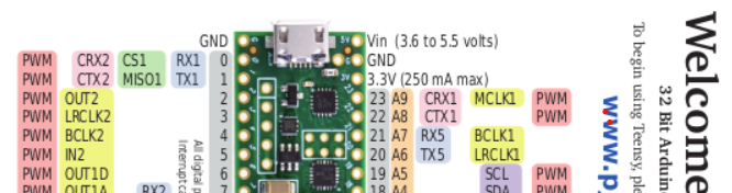
 defragster replied to the thread Freertos with teensy 4.0.Looking at the card the 23,22 will precede 0,1:
 -
-
Rrevati replied to the thread Freertos with teensy 4.0.My one can is connected to pin number 23,22 and second one 0,1 so in code which one will be can 1 and can2?
-
Ccharles789 reacted to TomChiron's post in the thread Teensy 4.1 anolog signal to FFT to 8 pins out ( noise floor help) with
 Like.
Good to hear that you already checked all these options. Good luck with the project! Looking forward to seeing progress and/or the final setup. These pneumanic cylinders sound impressive. I like such mechanical things.
Like.
Good to hear that you already checked all these options. Good luck with the project! Looking forward to seeing progress and/or the final setup. These pneumanic cylinders sound impressive. I like such mechanical things. -
 HermesTheNurse reacted to MarkT's post in the thread Connecting Teensy 4.0 + Teensy Audio Shield with Adafruit Class D Amplifier with Like.
The Audio shield has pads for connecting line-in and line-out - you need to connect line-out to the amp. As supplied these pads are unpopulated, so some soldering is needed. Some pin headers could be used, or just wire directly to a 3.5mm...
HermesTheNurse reacted to MarkT's post in the thread Connecting Teensy 4.0 + Teensy Audio Shield with Adafruit Class D Amplifier with Like.
The Audio shield has pads for connecting line-in and line-out - you need to connect line-out to the amp. As supplied these pads are unpopulated, so some soldering is needed. Some pin headers could be used, or just wire directly to a 3.5mm... -
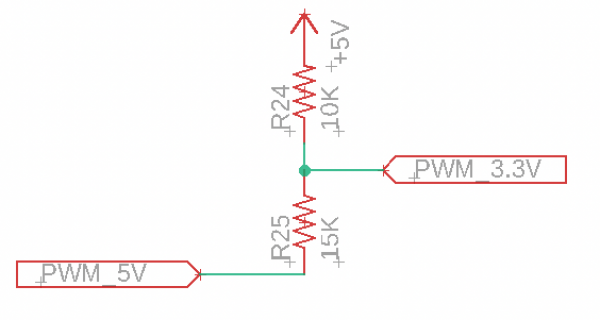
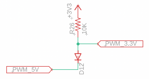
Jjmarsh replied to the thread PWM Voltage Conversion.That's what I would do (and have done on several occasions).
-
JHi folks, I would love a double check on something. I’m working on a project that I’m reading a 5V PWM signal into a 3.3V only input. The PWM signal is actively driven between GND and +5V and is “active low”, meaning I will see 0V when the PWM...
-
-
Bblinkypiper replied to the thread System works when powered by USB, but behaves weirdly on switching power supplies.Thanks everyone! So far it seems like putting all the wires between the MCU and the motor drive through the same ferrite bead, plus adding bypass caps on the inputs has solved the problem. Because the positional switches take >150ms to fall and...
-
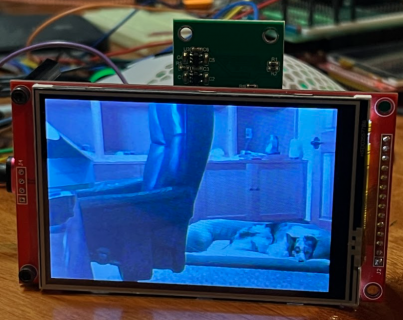
 Quick updates on CSI code: I now have more of it working with T4.1 and CSI running in VGA size, with PSRAM for frame buffer. I have more of it working now. With the VGA sketch, using OV7675 camera PSRAM, where f command is working, as is m and...
 -
 sbfreddie replied to the thread System works when powered by USB, but behaves weirdly on switching power supplies.I would also check for continuity between the power supply safety grounds and the V- supply pins of the Power Supplies to make sure you are not creating a ground loop between the safety ground and the Ground pins of the Teensy and Motor Driver...
 -
Jjrod305 replied to the thread U4 Chip gets extremely hot when 4.1 is connected to power..Thanks for reply, I was under the assumption pins 0-12 are PWM pins able to receive PWM signals , thus I connected PWM wire of servo motor to it . I’ve always used those pins, even to operate 4 servos at a time. I left only the servo PWM pin...
-
defragster reacted to KurtE's post in the thread New Camera Library for Teensy Micromod/4.1 with Like.
Quick updates on CSI code: I now have more of it working with T4.1 and CSI running in VGA size, with PSRAM for frame buffer. I have more of it working now. With the VGA sketch, using OV7675 camera PSRAM, where f command is working, as is m and...
-
 KurtE replied to the thread New Camera Library for Teensy Micromod/4.1.Quick updates on CSI code: I now have more of it working with T4.1 and CSI running in VGA size, with PSRAM for frame buffer. I have more of it working now. With the VGA sketch, using OV7675 camera PSRAM, where f command is working, as is m and...
 -
-
 wwatson replied to the thread Call to arms | Teensy + SDRAM = true.I had not thought of that. What's interesting is it works fine from flash memory on the MicroMod and T41. So maybe there is a conflict somewhere. I could speed up the bus rate and see if that changes any thing... Edit: Went from 2MHz to 24MHZ...
 -
Jjmarsh replied to the thread Call to arms | Teensy + SDRAM = true.Looks like flash is just barely too slow to keep up... unless there's code somewhere running directly from flash causing contention?
-
CChrisT replied to the thread ShiftPWM library compile error.That's marvellous @Paul, thank you so much (y)
-
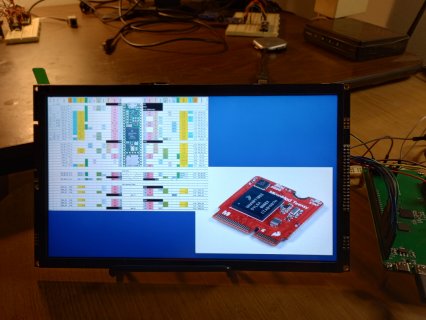
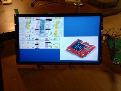
Have the SDRAM board wired up to the ER-TFT101-1 display. DMA is working on it as well as the MicroMod, sort of! This is the test sketch I am using modified to include SDRAM usage: #include "RA8876_t3.h" #include "SDRAM_t4.h" #include...
-
 PaulStoffregen replied to the thread ShiftPWM library compile error.I've committed a fix on github. https://github.com/PaulStoffregen/ShiftPWM/commit/4c25bfda72ac3cb99fc20ae7cb8c35aa8926e363 Sadly, this library isn't tested by my script that tries to compile all examples from all libraries because these...
 -
Have the SDRAM board wired up to the ER-TFT101-1 display. DMA is working on it as well as the MicroMod, sort of! This is the test sketch I am using modified to include SDRAM usage: #include "RA8876_t3.h" #include "SDRAM_t4.h" #include...
-
Have the SDRAM board wired up to the ER-TFT101-1 display. DMA is working on it as well as the MicroMod, sort of! This is the test sketch I am using modified to include SDRAM usage: #include "RA8876_t3.h" #include "SDRAM_t4.h" #include...
-
PaulStoffregen replied to the thread Two queues on i2s input not working.If you want me to investigate, please post another complete program to demonstrate the problem. Even if the change from the code you showed in msg #5 is trivial, I need you to understand I have a long history of wasting time not able to...
-
TTeensyPhonon replied to the thread Two queues on i2s input not working.I actually tested it with a bunch of values, and it only works if the number of blocks is odd. I think it comes from the fact that the input is stereo while the output is mono, so it is not possible for the input queues to allocate everything...
-
Bblinkypiper reacted to MarkT's post in the thread System works when powered by USB, but behaves weirdly on switching power supplies with Like.
Ideally all the wires from mcu to motor driver should go through the same ferrite so it removes common-mode interference but doesn't add differential mode interference. Definitely add 10nF to 100nF on those limit switch inputs next to the mcu...
-
PaulStoffregen replied to the thread Two queues on i2s input not working.For the sake of testing, I'd try allocating many more blocks, like 100. Then if you see your usage is in the 90s, you'll know one or more of the queues is hogging memory.
-
wwatson replied to the thread Call to arms | Teensy + SDRAM = true.Have the SDRAM board wired up to the ER-TFT101-1 display. DMA is working on it as well as the MicroMod, sort of! This is the test sketch I am using modified to include SDRAM usage: #include "RA8876_t3.h" #include "SDRAM_t4.h" #include...
-
-
MMarkT replied to the thread System works when powered by USB, but behaves weirdly on switching power supplies.Ideally all the wires from mcu to motor driver should go through the same ferrite so it removes common-mode interference but doesn't add differential mode interference. Definitely add 10nF to 100nF on those limit switch inputs next to the mcu...
-
MMarkT replied to the thread Two queues on i2s input not working.If the system is starved of blocks odd things can happen if something is freeing blocks at all, don't take the fact it "works" with 11 to mean its properly working, for if it were 12 would definitely work too.
-
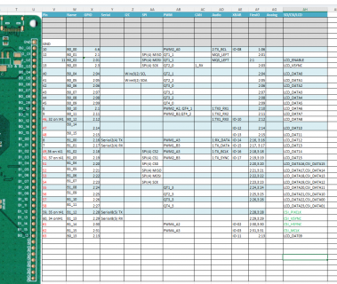
Merged: https://github.com/Defragster/EVKB_1060/blob/main/docs/DogBoneSDRAMv1.xlsx
-
RMerged: https://github.com/Defragster/EVKB_1060/blob/main/docs/DogBoneSDRAMv1.xlsx
-
Sorry, I did not go all the way up on the SS to those pins... I have now... Exactly. Pushed up current version to fork of defragsters github project and issued PR https://github.com/Defragster/EVKB_1060/pull/1
-
Merged: https://github.com/Defragster/EVKB_1060/blob/main/docs/DogBoneSDRAMv1.xlsx
-
defragster replied to the thread Call to arms | Teensy + SDRAM = true.Merged: https://github.com/Defragster/EVKB_1060/blob/main/docs/DogBoneSDRAMv1.xlsx
-
RSorry, I did not go all the way up on the SS to those pins... I have now... Exactly. Pushed up current version to fork of defragsters github project and issued PR https://github.com/Defragster/EVKB_1060/pull/1
-
Sorry, I did not go all the way up on the SS to those pins... I have now... Exactly. Pushed up current version to fork of defragsters github project and issued PR https://github.com/Defragster/EVKB_1060/pull/1
-
KurtE replied to the thread Call to arms | Teensy + SDRAM = true.Sorry, I did not go all the way up on the SS to those pins... I have now... Exactly. Pushed up current version to fork of defragsters github project and issued PR https://github.com/Defragster/EVKB_1060/pull/1
-
@KurtE here is the full list. Need to update B0_00 through B0_03 accordingly
-
Thanks, @mjs513 (and others), I updated again the dogbone... excel document all of the LCD pins on the right hand side of the board were filled in. I think it should look like: Will send the document back to you and/or could try to do PR with...
-
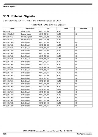
Jjmarsh replied to the thread Call to arms | Teensy + SDRAM = true.B0_00 is LCD_CLK, B0_01 is LCD_ENABLE, B0_02 is LCD_HSYNC. I guess you could have either a 24-bit LCD, or a 10/16 bit camera without running into conflicts. But still, not with the current board due to the missing CSI data pins.
-
RRezo replied to the thread Call to arms | Teensy + SDRAM = true.@KurtE here is the full list. Need to update B0_00 through B0_03 accordingly
-
-
KurtE replied to the thread Call to arms | Teensy + SDRAM = true.Thanks, @mjs513 (and others), I updated again the dogbone... excel document all of the LCD pins on the right hand side of the board were filled in. I think it should look like: Will send the document back to you and/or could try to do PR with...
-
-
@KurtE the dev board has all the eCLDIF pins exposed. Starting from B0_00 to B1_13 I believe. I posted here a few weeks back that I got it working on a 24 bit display with SDRAM.
-
Right, and the EVK board has the display wired at 16 bits to free up the rest of GPIO_B1
-
Right, and the EVK board has the display wired at 16 bits to free up the rest of GPIO_B1
-
RLCDIF, CSI, and PXP all have their own masters. Their priorities (against each other) are controlled by the SIM_MAIN NIC registers. The documentation hints that LCDIF has a bunch of cache memory tucked away inside of it, that isn't directly...
-
RRezo replied to the thread Call to arms | Teensy + SDRAM = true.Right, and the EVK board has the display wired at 16 bits to free up the rest of GPIO_B1
-
I wonder if there are any hints on this on how they use SDRAM with CSI in the 1050 document https://www.nxp.com/docs/en/application-note/AN12110.pdf
-
@KurtE the dev board has all the eCLDIF pins exposed. Starting from B0_00 to B1_13 I believe. I posted here a few weeks back that I got it working on a 24 bit display with SDRAM.
-
Jjmarsh replied to the thread Call to arms | Teensy + SDRAM = true.I think the way they organised the pins was intended for an 8-bit camera connected to CSI and a 16-bit (parallel) display connected to LCDIF. Anything higher in either case and you run out of pins due to them being shared between the modules.
-
RRezo replied to the thread Call to arms | Teensy + SDRAM = true.@KurtE the dev board has all the eCLDIF pins exposed. Starting from B0_00 to B1_13 I believe. I posted here a few weeks back that I got it working on a 24 bit display with SDRAM.