Latest activity
-
RI received my 74LVC245 chips and had some fun wiring this rat's nest up: This took care of the bad image when loading from FLASHMEM. Both FLASHMEM and SDRAM are working using 8-bit DMA. The image is correct and repeatable at 20MHz. I only...
-
 wwatson replied to the thread Call to arms | Teensy + SDRAM = true.I received my 74LVC245 chips and had some fun wiring this rat's nest up: This took care of the bad image when loading from FLASHMEM. Both FLASHMEM and SDRAM are working using 8-bit DMA. The image is correct and repeatable at 20MHz. I only...
 -
-
Was playing around jpegdec library and did a comparison of using PROGMEM vs SDRAM (running at 198Mhz) FLash TEST full sized decode in 28350 us half sized decode in 21260 us quarter sized decode in 7320 us eighth sized decode in 6104 us SDRAM...
-
 PaulS replied to the thread multiple teensy's.Can you share the complete code that "stopped working"? Paul
 -
 PaulStoffregen replied to the thread Teensy 4.1 How to start using DMA?.OctoWS2811 on Teensy 4 is probably the most complicated DMA of any library. You'd probably be better off reading the DMA code from a much simpler library, like WS2812Serial. To answer this specific question, 16K is the distance between each of...
 -
-
Mmorry replied to the thread multiple teensy's.FYI I made these changes to code and it stopped working all together maybe because I have a teensy3.2 not 4 still have problem got the data line issues figured out but in FPP sequences play correct in test mode but when I go to play mode lights...
-
Bbiomurph replied to the thread DAC Output.I am exploring the DACs on Teensy 3.6 (yes, I know it is EOL, but I am in need of a microcontroller with two on-board DACs). When you say that any noise in the power supply will be coupled to the output, I totally get that, though have not seen...
-
RRezo replied to the thread Call to arms | Teensy + SDRAM = true.@mjs513 I think the PXP can help you with the color conversion, and it might be faster as well. But either way it will be done async and won’t require any CPU for it.
-
RWas playing around jpegdec library and did a comparison of using PROGMEM vs SDRAM (running at 198Mhz) FLash TEST full sized decode in 28350 us half sized decode in 21260 us quarter sized decode in 7320 us eighth sized decode in 6104 us SDRAM...
-
 Was playing around jpegdec library and did a comparison of using PROGMEM vs SDRAM (running at 198Mhz) FLash TEST full sized decode in 28350 us half sized decode in 21260 us quarter sized decode in 7320 us eighth sized decode in 6104 us SDRAM...
 -
 mjs513 replied to the thread Call to arms | Teensy + SDRAM = true.Was playing around jpegdec library and did a comparison of using PROGMEM vs SDRAM (running at 198Mhz) FLash TEST full sized decode in 28350 us half sized decode in 21260 us quarter sized decode in 7320 us eighth sized decode in 6104 us SDRAM...
 -
Jjkoffman replied to the thread PWM Voltage Conversion.It’s an attempt to save board space and for simplicity. But you’re winning me over. I just need to find a suitable chip and start planning around that.
-
PaulStoffregen replied to the thread PWM Voltage Conversion.I don't understand the reluctance to use a proper 5V tolerant buffer chip. For 3 signals, you'd need 1 chip and 1 decoupling capacitor for good quality results. Seems better than using 6 parts for marginal quality waveforms.
-
Jjkoffman replied to the thread PWM Voltage Conversion.Hi all, I appreciate the replies. @Paul very interesting, thank you for the insight. This circuit will be directly feeding an input pin on a T4.0. My plan is to try to decipher 3 channels of PWM using FreqMeasureMulti. If possible I’d switch...
-
Eemiel.h replied to the thread Teensy 4.1 How to start using DMA?.Hi, I'm trying to understand how the DMA's are used on the Teensy 4 in the OctoWS2811 library. By looking at the following lines I can decipher that dma1 is used to set the pins high at the start of the WS2811 waveform, dma2 to set it high or low...
-
Bblinkypiper reacted to sbfreddie's post in the thread System works when powered by USB, but behaves weirdly on switching power supplies with
 Like.
I would also check for continuity between the power supply safety grounds and the V- supply pins of the Power Supplies to make sure you are not creating a ground loop between the safety ground and the Ground pins of the Teensy and Motor Driver...
Like.
I would also check for continuity between the power supply safety grounds and the V- supply pins of the Power Supplies to make sure you are not creating a ground loop between the safety ground and the Ground pins of the Teensy and Motor Driver... -
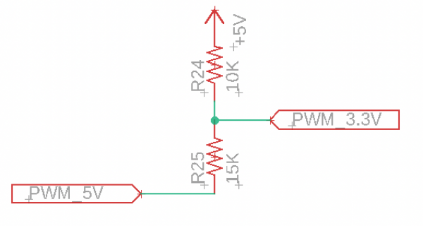
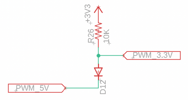
PaulStoffregen replied to the thread PWM Voltage Conversion.This circuit has some limitations which may or may not be a problem. Understanding the issues can help you to anticipate whether it will work well enough, or if those limitations will cause problems. The main issue is the diode's forward...
-
AAngelo replied to the thread Freertos with teensy 4.0.Simply add #define DEBUG_MODE in your skech, before #include "MCP_CAN.h" Rebuild the project, run, and check the messages on serial port
-
PaulStoffregen replied to the thread Two queues on i2s input not working.Yes, this is expected behavior. If you leave any record queue active but your program doesn't remove the data, incoming audio quickly uses up the available memory. It is not a bug in the audio library. This is the way queues work.
-
Rrevati replied to the thread Freertos with teensy 4.0.Can you give example for this I am actually not understanding
-
AAngelo replied to the thread Freertos with teensy 4.0.Again, add the #define DEBUG_MODE. The driver will send additional error messages on serial port.
-
Rrevati replied to the thread Freertos with teensy 4.0.If I am changing cs pin, then mcp2515 initialization is not successful.
-
AAngelo replied to the thread Freertos with teensy 4.0.Pin 16 on MCP2515 is CS. Check with ohm-meter where it is connected on Arduino connectors. And try to use an oscilloscope to check the CAN-L and CAN-H line. Is the message really sent on the lines ???
-
Rrevati replied to the thread Freertos with teensy 4.0.What about pin number ?
-
AAngelo replied to the thread Freertos with teensy 4.0.Try to add #define DEBUG_MODE in your code. MCP_CAN will send messages during init.
-
TTeensyPhonon replied to the thread Two queues on i2s input not working.The code I used is : #include <Audio.h> #include <arm_const_structs.h> #include <utility/imxrt_hw.h> #include <SD.h> #include <SPI.h> File dataFile; const int chipSelect = BUILTIN_SDCARD...
-
Rrevati replied to the thread Freertos with teensy 4.0.if I am changing pin number 9 to 10 then I am not able to send the message through CAN but if I am changing that to 9 can initialization is failed but able to send the message so confused in pin configuration.
-
AAngelo replied to the thread Freertos with teensy 4.0.Check https://wiki.elecrow.com/index.php?title=CAN-BUS_Shield I can read this in the example code // the cs pin of the version after v1.1 is default to D9 // v0.9b and v1.0 is default D10 const int SPI_CS_PIN = 9; MCP_CAN CAN(SPI_CS_PIN)...
-
Rrevati replied to the thread Freertos with teensy 4.0.Thank you. what about can shield v1.5 what is cs, INT pin so that I can communicate can shield v1.5 which is connected to Arduino board and one can controller which is connected to teensy board.
-
AAngelo replied to the thread Freertos with teensy 4.0.Check example https://github.com/skpang/Teensy41_triple_CAN_ETH_GPS/blob/main/Teensy41_triple_CAN_demo/Teensy41_triple_CAN_demo.ino FlexCAN_T4<CAN2, RX_SIZE_256, TX_SIZE_16> can2; FlexCAN_T4<CAN1, RX_SIZE_256, TX_SIZE_16> can1; can1 is on...
-
Rrevati replied to the thread Freertos with teensy 4.0.My question is like I have connected two can controllers one with 23,22 pin number and one with 0,1 pin number suppose I am connecting either of them can controller so in code will it matter which can controller I am defining in code? that is my...
-
AAngelo replied to the thread Freertos with teensy 4.0.SKPANG made various CAN boards for both Teensy 4.0 and 4.1. They have schematics and example sketches https://www.skpang.co.uk
-
 ninja2 replied to the thread RTC on Wire2 in multi-tab sketch.FWIW I posted this on the Arduino forum, and with good guidance I found the solution, Look here if you're interested: DS1307RTC library and Wire2
 -
Rrevati replied to the thread Freertos with teensy 4.0.in code what we should declare if we are any one of this can pins? for 0,1 and 23,22 that I want to know.
-
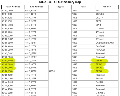
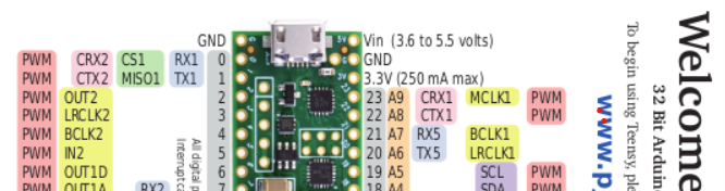
 defragster replied to the thread Freertos with teensy 4.0.Looking at the card the 23,22 will precede 0,1:
 -
-
Rrevati replied to the thread Freertos with teensy 4.0.My one can is connected to pin number 23,22 and second one 0,1 so in code which one will be can 1 and can2?
-
Ccharles789 reacted to TomChiron's post in the thread Teensy 4.1 anolog signal to FFT to 8 pins out ( noise floor help) with Like.
Good to hear that you already checked all these options. Good luck with the project! Looking forward to seeing progress and/or the final setup. These pneumanic cylinders sound impressive. I like such mechanical things.
-
 HermesTheNurse reacted to MarkT's post in the thread Connecting Teensy 4.0 + Teensy Audio Shield with Adafruit Class D Amplifier with Like.
The Audio shield has pads for connecting line-in and line-out - you need to connect line-out to the amp. As supplied these pads are unpopulated, so some soldering is needed. Some pin headers could be used, or just wire directly to a 3.5mm...
HermesTheNurse reacted to MarkT's post in the thread Connecting Teensy 4.0 + Teensy Audio Shield with Adafruit Class D Amplifier with Like.
The Audio shield has pads for connecting line-in and line-out - you need to connect line-out to the amp. As supplied these pads are unpopulated, so some soldering is needed. Some pin headers could be used, or just wire directly to a 3.5mm... -
Jjmarsh replied to the thread PWM Voltage Conversion.That's what I would do (and have done on several occasions).
-
JHi folks, I would love a double check on something. I’m working on a project that I’m reading a 5V PWM signal into a 3.3V only input. The PWM signal is actively driven between GND and +5V and is “active low”, meaning I will see 0V when the PWM...
-
-
Bblinkypiper replied to the thread System works when powered by USB, but behaves weirdly on switching power supplies.Thanks everyone! So far it seems like putting all the wires between the MCU and the motor drive through the same ferrite bead, plus adding bypass caps on the inputs has solved the problem. Because the positional switches take >150ms to fall and...
-
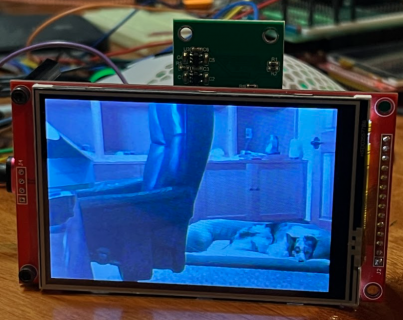
Quick updates on CSI code: I now have more of it working with T4.1 and CSI running in VGA size, with PSRAM for frame buffer. I have more of it working now. With the VGA sketch, using OV7675 camera PSRAM, where f command is working, as is m and...
-
 sbfreddie replied to the thread System works when powered by USB, but behaves weirdly on switching power supplies.I would also check for continuity between the power supply safety grounds and the V- supply pins of the Power Supplies to make sure you are not creating a ground loop between the safety ground and the Ground pins of the Teensy and Motor Driver...
 -
Jjrod305 replied to the thread U4 Chip gets extremely hot when 4.1 is connected to power..Thanks for reply, I was under the assumption pins 0-12 are PWM pins able to receive PWM signals , thus I connected PWM wire of servo motor to it . I’ve always used those pins, even to operate 4 servos at a time. I left only the servo PWM pin...
-
defragster reacted to KurtE's post in the thread New Camera Library for Teensy Micromod/4.1 with Like.
Quick updates on CSI code: I now have more of it working with T4.1 and CSI running in VGA size, with PSRAM for frame buffer. I have more of it working now. With the VGA sketch, using OV7675 camera PSRAM, where f command is working, as is m and...
-
KurtE replied to the thread New Camera Library for Teensy Micromod/4.1.Quick updates on CSI code: I now have more of it working with T4.1 and CSI running in VGA size, with PSRAM for frame buffer. I have more of it working now. With the VGA sketch, using OV7675 camera PSRAM, where f command is working, as is m and...
-
-
wwatson replied to the thread Call to arms | Teensy + SDRAM = true.I had not thought of that. What's interesting is it works fine from flash memory on the MicroMod and T41. So maybe there is a conflict somewhere. I could speed up the bus rate and see if that changes any thing... Edit: Went from 2MHz to 24MHZ...
-
Jjmarsh replied to the thread Call to arms | Teensy + SDRAM = true.Looks like flash is just barely too slow to keep up... unless there's code somewhere running directly from flash causing contention?
-
CChrisT replied to the thread ShiftPWM library compile error.That's marvellous @Paul, thank you so much (y)
-
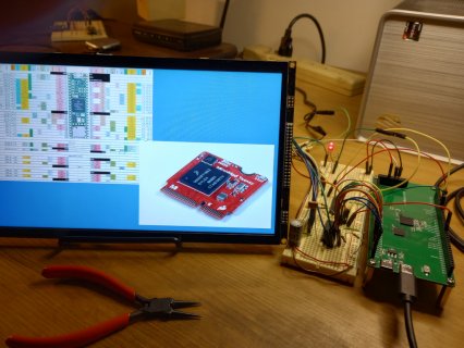
Have the SDRAM board wired up to the ER-TFT101-1 display. DMA is working on it as well as the MicroMod, sort of! This is the test sketch I am using modified to include SDRAM usage: #include "RA8876_t3.h" #include "SDRAM_t4.h" #include...