Latest activity
-
 PaulStoffregen replied to the thread USB connection from D+ / D- pins with external supply.This really should work. Any chance the wire colors aren't matched up to the corresponding pins inside the cable? (for example, white and green really connected to GND and +5V)
 -
HHaybur posted the thread Teensy 4.1 + Audio Adapter + FastLED + Custom PCB = Magic in Blog Project Submission.I saw ByronAP posted his pixel controller and thought I'd share mine too with pictures/videos for you Paul! I've been making LEDs visualize music with Teensys since 2016/17 I think and I started the company diod.design. In the album below, I...
-
Nnitrojam posted the thread USB connection from D+ / D- pins with external supply in Technical Support & Questions.Hello, I am running a Teensy 4.1 inside a box, and it is powered from a PSU (picoPSU for those who know it) on 5V. I have a custom USB cable (with 5V disconnected) which I connect from the Teensy USB port tto my PC in order to program the...
-
PaulStoffregen replied to the thread U4 Chip gets extremely hot when 4.1 is connected to power..Unfortunately, no. Nobody can really give a clear definitive answer about what happened, or even might have happened. First, we just don't know enough. We can't see what type of motor you're using. Maybe it's something very small like on this...
-
 PaulS replied to the thread BUG: OneWire missing GPIO definition with ESP32-C6.Here is the arduino-esp32 repository. You can file an issue here. And this is perhaps a usable library for OneWire on ESP32. Paul
 -
 I received my 74LVC245 chips and had some fun wiring this rat's nest up: This took care of the bad image when loading from FLASHMEM. Both FLASHMEM and SDRAM are working using 8-bit DMA. The image is correct and repeatable at 20MHz. I only...
 -
 I received my 74LVC245 chips and had some fun wiring this rat's nest up: This took care of the bad image when loading from FLASHMEM. Both FLASHMEM and SDRAM are working using 8-bit DMA. The image is correct and repeatable at 20MHz. I only...
 -
Jjrod305 replied to the thread U4 Chip gets extremely hot when 4.1 is connected to power..Very true sorry for the misphrasing
-
NNantonos replied to the thread U4 Chip gets extremely hot when 4.1 is connected to power..No, they are PWM pins able to generate PWM signals.
-
Ddr_glenn replied to the thread BUG: OneWire missing GPIO definition with ESP32-C6.Sorry, but w/o reading deeply I didn't realize that OneWire was originally only for Teensy devices. I'm new to ESP32 and never used Arduino, so I was surprised to find libraries that can be compiled for such a large variety of controllers. I...
-
NNantonos replied to the thread BUG: OneWire missing GPIO definition with ESP32-C6.This might be caused by a missing util/OneWire_direct_gpio.h Note the comment in that code: #elif defined(ARDUINO_ARCH_ESP8266) // Special note: I depend on the ESP community to maintain these definitions and // submit good pull requests...
-
 BriComp replied to the thread BUG: OneWire missing GPIO definition with ESP32-C6.I think you ought to go onto an ESP32 site for that sort of answer. It's not applicable to Teensy.
 -
Mmykle posted the thread is TeensyTransfer built for Apple Silicon? in Technical Support & Questions.Hi, I'm trying to find the teensytransfer utility, so I can throw a sound on my good ol' Prop Shield. The github repo for this tool seem to be shifting around a little bit; a lot of pointers to that repo here in the forums are 404 . Googling...
-
Ddr_glenn posted the thread BUG: OneWire missing GPIO definition with ESP32-C6 in Suggestions & Bug Reports.I am using OneWire 2.3.7 in Arduino IDE 2.3.2 with a "SparkFun ESP32-C6 WROOM Qwiic Pocket". The sketch compile fails with: Arduino\libraries\OneWire\util/OneWire_direct_gpio.h:134:17: error: 'GPIO' was not declared in this scope; did you mean...
-
 I received my 74LVC245 chips and had some fun wiring this rat's nest up: This took care of the bad image when loading from FLASHMEM. Both FLASHMEM and SDRAM are working using 8-bit DMA. The image is correct and repeatable at 20MHz. I only...
 -
RI received my 74LVC245 chips and had some fun wiring this rat's nest up: This took care of the bad image when loading from FLASHMEM. Both FLASHMEM and SDRAM are working using 8-bit DMA. The image is correct and repeatable at 20MHz. I only...
-
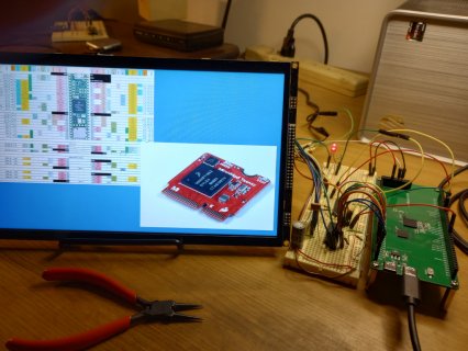
 wwatson replied to the thread Call to arms | Teensy + SDRAM = true.I received my 74LVC245 chips and had some fun wiring this rat's nest up: This took care of the bad image when loading from FLASHMEM. Both FLASHMEM and SDRAM are working using 8-bit DMA. The image is correct and repeatable at 20MHz. I only...
 -
-
Was playing around jpegdec library and did a comparison of using PROGMEM vs SDRAM (running at 198Mhz) FLash TEST full sized decode in 28350 us half sized decode in 21260 us quarter sized decode in 7320 us eighth sized decode in 6104 us SDRAM...
-
PaulS replied to the thread multiple teensy's.Can you share the complete code that "stopped working"? Paul
-
PaulStoffregen replied to the thread Teensy 4.1 How to start using DMA?.OctoWS2811 on Teensy 4 is probably the most complicated DMA of any library. You'd probably be better off reading the DMA code from a much simpler library, like WS2812Serial. To answer this specific question, 16K is the distance between each of...
-
-
Mmorry replied to the thread multiple teensy's.FYI I made these changes to code and it stopped working all together maybe because I have a teensy3.2 not 4 still have problem got the data line issues figured out but in FPP sequences play correct in test mode but when I go to play mode lights...
-
Bbiomurph replied to the thread DAC Output.I am exploring the DACs on Teensy 3.6 (yes, I know it is EOL, but I am in need of a microcontroller with two on-board DACs). When you say that any noise in the power supply will be coupled to the output, I totally get that, though have not seen...
-
RRezo replied to the thread Call to arms | Teensy + SDRAM = true.@mjs513 I think the PXP can help you with the color conversion, and it might be faster as well. But either way it will be done async and won’t require any CPU for it.
-
RWas playing around jpegdec library and did a comparison of using PROGMEM vs SDRAM (running at 198Mhz) FLash TEST full sized decode in 28350 us half sized decode in 21260 us quarter sized decode in 7320 us eighth sized decode in 6104 us SDRAM...
-
Was playing around jpegdec library and did a comparison of using PROGMEM vs SDRAM (running at 198Mhz) FLash TEST full sized decode in 28350 us half sized decode in 21260 us quarter sized decode in 7320 us eighth sized decode in 6104 us SDRAM...
-
mjs513 replied to the thread Call to arms | Teensy + SDRAM = true.Was playing around jpegdec library and did a comparison of using PROGMEM vs SDRAM (running at 198Mhz) FLash TEST full sized decode in 28350 us half sized decode in 21260 us quarter sized decode in 7320 us eighth sized decode in 6104 us SDRAM...
-
Jjkoffman replied to the thread PWM Voltage Conversion.It’s an attempt to save board space and for simplicity. But you’re winning me over. I just need to find a suitable chip and start planning around that.
-
PaulStoffregen replied to the thread PWM Voltage Conversion.I don't understand the reluctance to use a proper 5V tolerant buffer chip. For 3 signals, you'd need 1 chip and 1 decoupling capacitor for good quality results. Seems better than using 6 parts for marginal quality waveforms.
-
Jjkoffman replied to the thread PWM Voltage Conversion.Hi all, I appreciate the replies. @Paul very interesting, thank you for the insight. This circuit will be directly feeding an input pin on a T4.0. My plan is to try to decipher 3 channels of PWM using FreqMeasureMulti. If possible I’d switch...
-
Eemiel.h replied to the thread Teensy 4.1 How to start using DMA?.Hi, I'm trying to understand how the DMA's are used on the Teensy 4 in the OctoWS2811 library. By looking at the following lines I can decipher that dma1 is used to set the pins high at the start of the WS2811 waveform, dma2 to set it high or low...
-
Bblinkypiper reacted to sbfreddie's post in the thread System works when powered by USB, but behaves weirdly on switching power supplies with
 Like.
I would also check for continuity between the power supply safety grounds and the V- supply pins of the Power Supplies to make sure you are not creating a ground loop between the safety ground and the Ground pins of the Teensy and Motor Driver...
Like.
I would also check for continuity between the power supply safety grounds and the V- supply pins of the Power Supplies to make sure you are not creating a ground loop between the safety ground and the Ground pins of the Teensy and Motor Driver... -
PaulStoffregen replied to the thread PWM Voltage Conversion.This circuit has some limitations which may or may not be a problem. Understanding the issues can help you to anticipate whether it will work well enough, or if those limitations will cause problems. The main issue is the diode's forward...
-
AAngelo replied to the thread Freertos with teensy 4.0.Simply add #define DEBUG_MODE in your skech, before #include "MCP_CAN.h" Rebuild the project, run, and check the messages on serial port
-
PaulStoffregen replied to the thread Two queues on i2s input not working.Yes, this is expected behavior. If you leave any record queue active but your program doesn't remove the data, incoming audio quickly uses up the available memory. It is not a bug in the audio library. This is the way queues work.
-
Rrevati replied to the thread Freertos with teensy 4.0.Can you give example for this I am actually not understanding
-
AAngelo replied to the thread Freertos with teensy 4.0.Again, add the #define DEBUG_MODE. The driver will send additional error messages on serial port.
-
Rrevati replied to the thread Freertos with teensy 4.0.If I am changing cs pin, then mcp2515 initialization is not successful.
-
AAngelo replied to the thread Freertos with teensy 4.0.Pin 16 on MCP2515 is CS. Check with ohm-meter where it is connected on Arduino connectors. And try to use an oscilloscope to check the CAN-L and CAN-H line. Is the message really sent on the lines ???
-
Rrevati replied to the thread Freertos with teensy 4.0.What about pin number ?
-
AAngelo replied to the thread Freertos with teensy 4.0.Try to add #define DEBUG_MODE in your code. MCP_CAN will send messages during init.
-
TTeensyPhonon replied to the thread Two queues on i2s input not working.The code I used is : #include <Audio.h> #include <arm_const_structs.h> #include <utility/imxrt_hw.h> #include <SD.h> #include <SPI.h> File dataFile; const int chipSelect = BUILTIN_SDCARD...
-
Rrevati replied to the thread Freertos with teensy 4.0.if I am changing pin number 9 to 10 then I am not able to send the message through CAN but if I am changing that to 9 can initialization is failed but able to send the message so confused in pin configuration.
-
AAngelo replied to the thread Freertos with teensy 4.0.Check https://wiki.elecrow.com/index.php?title=CAN-BUS_Shield I can read this in the example code // the cs pin of the version after v1.1 is default to D9 // v0.9b and v1.0 is default D10 const int SPI_CS_PIN = 9; MCP_CAN CAN(SPI_CS_PIN)...
-
Rrevati replied to the thread Freertos with teensy 4.0.Thank you. what about can shield v1.5 what is cs, INT pin so that I can communicate can shield v1.5 which is connected to Arduino board and one can controller which is connected to teensy board.
-
AAngelo replied to the thread Freertos with teensy 4.0.Check example https://github.com/skpang/Teensy41_triple_CAN_ETH_GPS/blob/main/Teensy41_triple_CAN_demo/Teensy41_triple_CAN_demo.ino FlexCAN_T4<CAN2, RX_SIZE_256, TX_SIZE_16> can2; FlexCAN_T4<CAN1, RX_SIZE_256, TX_SIZE_16> can1; can1 is on...
-
Rrevati replied to the thread Freertos with teensy 4.0.My question is like I have connected two can controllers one with 23,22 pin number and one with 0,1 pin number suppose I am connecting either of them can controller so in code will it matter which can controller I am defining in code? that is my...
-
AAngelo replied to the thread Freertos with teensy 4.0.SKPANG made various CAN boards for both Teensy 4.0 and 4.1. They have schematics and example sketches https://www.skpang.co.uk
-
 ninja2 replied to the thread RTC on Wire2 in multi-tab sketch.FWIW I posted this on the Arduino forum, and with good guidance I found the solution, Look here if you're interested: DS1307RTC library and Wire2
 -
Rrevati replied to the thread Freertos with teensy 4.0.in code what we should declare if we are any one of this can pins? for 0,1 and 23,22 that I want to know.
-
defragster replied to the thread Freertos with teensy 4.0.Looking at the card the 23,22 will precede 0,1:
-