Latest activity
-
 Starting to have some success with the match :D I changed: _pflexio->SHIFTCFG[_fshifter_jpeg] = FLEXIO_SHIFTCFG_PWIDTH(31) | FLEXIO_SHIFTCFG_INSRC; To PMOD to transfer 32 bits instead of 16 and things started to work. Although it...
 -
NNantonos replied to the thread How to do "pass-through" knobs on synth with presets?.You would normally want to be able to pass the preset value in both directions (if increasing the knob, where the preset value is higher than currently; and if decreasing the knob, where the preset value is lower than currently).
-
 KurtE replied to the thread New Camera Library for Teensy Micromod/4.1.Starting to have some success with the match :D I changed: _pflexio->SHIFTCFG[_fshifter_jpeg] = FLEXIO_SHIFTCFG_PWIDTH(31) | FLEXIO_SHIFTCFG_INSRC; To PMOD to transfer 32 bits instead of 16 and things started to work. Although it...
 -
-
DDave71 replied to the thread Button press output errors - assistance needed.Great, thanks for that. Seems to have cured the issue. 50+ button pushes later and I’ve got 100% success rate thanks again!
-
Mmborgerson replied to the thread USBHost_t36 slow reception of incoming data.I made an interesting discovery this morning: If I put a powered USB 3.0 hub between the Lepton T3.2 and the Host Serial port of the T4.1, the data upload speed increases dramatically! Without the hub, the upload of a 38400-byte frame takes...
-
Mmborgerson replied to the thread USBHost_t36 slow reception of incoming data.I'm having other issues with the HostSerial receive that are puzzling. The T3.2 device sends good frames to my PC, but when I try to read with HostSerial, I get lots of garbage data or no data at all in the destination buffer. I think I may...
-
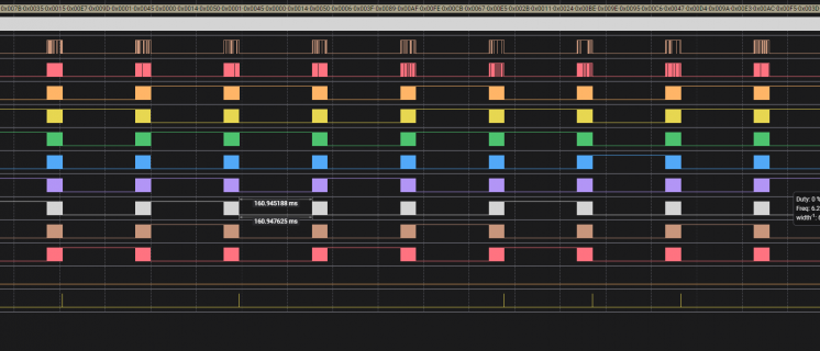
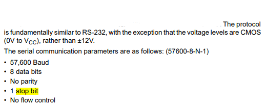
 MichaelMeissner replied to the thread Interfacing a 3.3V RS-232 directly in Teensy 4.1.While RS-232 has higher voltage, on the Teensy 4.0/4.1/micromod (and on the legacy Teensy 3.0,3.6, and LC), the voltage on the TX and RX pins must be 3.3 volts. If you use higher voltage, you risk burning out the Teensy. Only on the legacy...
 -
 BriComp replied to the thread Interfacing a 3.3V RS-232 directly in Teensy 4.1.CMOS Voltages can be as high as 15V. How much is Vcc on the device?
 -
 luni replied to the thread uploading hex file via teensy loader.Since you are doing a c# application you might be interested in TeensySharp. https://github.com/luni64/TeensySharp Getting a list of currently connected Teensies is a simple as this: var Watcher = new TeensyWatcher(); foreach (var Teensy in...
 -
MichaelMeissner reacted to Dogbone06's post in the thread Teensy 4.1 3.3V clock battery for keeping time with
 Like.
It works! Thanks for the help. For anyone else with the same problem as I had. Just add this: time_t getTeensy3Time() { return Teensy3Clock.get(); } In setup or your custom init function place do: setSyncProvider(getTeensy3Time); Ignore the...
Like.
It works! Thanks for the help. For anyone else with the same problem as I had. Just add this: time_t getTeensy3Time() { return Teensy3Clock.get(); } In setup or your custom init function place do: setSyncProvider(getTeensy3Time); Ignore the... -
DDogbone06 replied to the thread Teensy 4.1 3.3V clock battery for keeping time.It works! Thanks for the help. For anyone else with the same problem as I had. Just add this: time_t getTeensy3Time() { return Teensy3Clock.get(); } In setup or your custom init function place do: setSyncProvider(getTeensy3Time); Ignore the...
-
 First again thanks for the input. So far I am not having much luck. probably something stupid I am doing and even more likely probably in some of the things I don't understand properly. When I setup the initial FlexIO, the main shifter is...
 -
First again thanks for the input. So far I am not having much luck. probably something stupid I am doing and even more likely probably in some of the things I don't understand properly. When I setup the initial FlexIO, the main shifter is...
-
KurtE replied to the thread New Camera Library for Teensy Micromod/4.1.First again thanks for the input. So far I am not having much luck. probably something stupid I am doing and even more likely probably in some of the things I don't understand properly. When I setup the initial FlexIO, the main shifter is...
-
Nnitrojam posted the thread Interfacing a 3.3V RS-232 directly in Teensy 4.1 in Technical Support & Questions.I know that most of the time RS-232 has a voltage > 3.3v but I do have a device that has a RS232 "like" interface which has a maximum 3.3V output (Vcc). As a consequence, would it be possible to interact with it from Serial1 pins for example ...
-
-
UUnhappyWithoutU replied to the thread U2 and D4 hot, 3.3v shorted to GND.Wouldnt it make sense that it's the bootloader Chip itself? Since it's not booting at All even when the 3.3v still exist
-
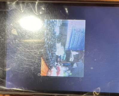
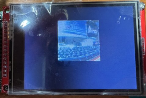
Ok all been at it some more with trying out scaling and rotation took most of yesterday to figure out. Did find that just using a macro to set the corners never changed the actual registers so initially things were screwy, so added a function to...
-
Amazing work Mike! Now get the touchscreen to work and try to scale in-out using a gesture ;)
-
Bbillypeoples replied to the thread Drawing FFT spectrum smoothly on TFT.To smoothly draw the FFT spectrum on your TFT screen without blinking and quickly, you can use a technique called full spectrum extraction. Instead of redrawing each line individually, you can calculate the changes in the spectrum and update the...
-
TThundercat replied to the thread New Teensy 4.0 Suddenly Not Recognized.Thank you Paul. No external PSU. Power is being taken directly from the VIN pin to the regulator, which is onboard the PCB; it's 2A as I recall. Only reason for the regulator is the unit has 4 RGB buttons with 3 LEDs each, so 12 LEDs, which...
-
TThundercat reacted to PaulStoffregen's post in the thread New Teensy 4.0 Suddenly Not Recognized with Like.
Could you explain how the power supply works? Is all the board's power coming from the USB cable connected to Teensy? Or is external power connected (maybe not shown on this schematic)?
-
Ppaoloboatto replied to the thread uploading hex file via teensy loader.I have another question: the string contains the USB port details i.e -port=usb:0/140000/0/1. However this port can change and I don't know how to find it under windows. As an example when downloading the firmware onto ES32 the string contains...
-
 PaulStoffregen replied to the thread New Teensy 4.0 Suddenly Not Recognized.Could you explain how the power supply works? Is all the board's power coming from the USB cable connected to Teensy? Or is external power connected (maybe not shown on this schematic)?
 -
RRezo replied to the thread T4 Pixel Pipeline Library.Amazing work Mike! Now get the touchscreen to work and try to scale in-out using a gesture ;)
-
ROk all been at it some more with trying out scaling and rotation took most of yesterday to figure out. Did find that just using a macro to set the corners never changed the actual registers so initially things were screwy, so added a function to...
-
TThundercat replied to the thread New Teensy 4.0 Suddenly Not Recognized.In the interest of discovery, I am posting the schematic for the unit in question. I won't keep it up too long, but hopefully it can help figure this out. Thanks, Mike
-
-
Ok all been at it some more with trying out scaling and rotation took most of yesterday to figure out. Did find that just using a macro to set the corners never changed the actual registers so initially things were screwy, so added a function to...
-
mjs513 replied to the thread T4 Pixel Pipeline Library.Ok all been at it some more with trying out scaling and rotation took most of yesterday to figure out. Did find that just using a macro to set the corners never changed the actual registers so initially things were screwy, so added a function to...
-
-
TThundercat replied to the thread New Teensy 4.0 Suddenly Not Recognized.Just FYI I'm now at 5 "defunct" Teensys and main boards...wish I wouldn't have already soldered them into the main boards. Obviously there's something going on here. Per Paul's suggestion I tried a different USB cable, and port, but no joy...
-
TThundercat replied to the thread New Teensy 4.0 Suddenly Not Recognized.So I checked out that thread that @PaulS shared; it seems there is something similar happening for me, but with the Teensy 4.0s. And not all of them. At least the older ones didn't have an issue. I've posted a question there and linked to this...
-
TThundercat replied to the thread Lockable Teensy 4.1 "bricks" after performing the "Lock Security Sketch".Could any of this apply to a Teensy 4.0? Doesn't have pins 24-25 but I'm getting similar issues on some - not all - lockable Teensy 4s bought in the last few months. I share about it in this thread. Thanks; I'm getting a bit desperate with...
-
TThundercat replied to the thread New Teensy 4.0 Suddenly Not Recognized.Apologies I misread your post. I’ll read through your link and check it out. Many thanks!
-
TThundercat replied to the thread New Teensy 4.0 Suddenly Not Recognized.Good insight. Yes, all the hardware is lockable Teensys. However, some failed prior to even going past first of 3 locking procedures. In other words they weren’t even yet locked. Thank you.
-
TAre all the failures happening with locked Teensys? Given nobody here has seen any code, schematics, etc. of anything you're using, the chances of anyone having any insight into the problem is very low.
-
Jjmarsh replied to the thread New Teensy 4.0 Suddenly Not Recognized.Are all the failures happening with locked Teensys? Given nobody here has seen any code, schematics, etc. of anything you're using, the chances of anyone having any insight into the problem is very low.
-
NGuys, I am tasked to prove that the ADC sampling rate of Teensy4.1 is 1MSPS or something close. Part of the project is about when the ADC, say A0 is connected to the signal generator and I supply frequencies between 5kHz and 10kHz to the teensy ...
-
TThundercat replied to the thread New Teensy 4.0 Suddenly Not Recognized.Thank you. The design works. I have units running on this PCB no problem. The PCB is also an nth generation derivative from previously working designs. So I have perfectly working units on this same run of PCBs. I’ve never had a teensy just...
-
TI understand your frustration... Is this thread somehow applicable to your design? Paul
-
 Given it's a non-production board I think it would be fine to skip the current limiter / ESD protection. The 4.0 devboard works fine in host mode but I always either use a hub or make sure not to hotplug anything directly to the board, just to be...
 -
BBakhanbeigi replied to the thread NixOs - Unable find Teensy Loader..Thanks for the answer, it seems adding that line solved that issue. But now it can not find the libudev.so.1 AVAILABLE: jlink, teensy-cli, teensy-gui CURRENT: upload_protocol = teensy-cli Rebooting... teensy_reboot: error while loading shared...
-
JHello, I'm building a small 2 in 2 out midi interface with a teensy 3.6. 2 questions: is it possible to power the teensy by the midi in cable? Is it possible to automatically switch between USB power supply and midi power supply? I would like to...
-
Jjmarsh replied to the thread Call to arms | Teensy + SDRAM = true.Given it's a non-production board I think it would be fine to skip the current limiter / ESD protection. The 4.0 devboard works fine in host mode but I always either use a hub or make sure not to hotplug anything directly to the board, just to be...
-
AAngelo replied to the thread What is 'State of the Art' for IMU + GPS on teensy 3.x 4.x.A good IMU+GPS integration could be found on the Ardupilot project. It is mainly based on STM32 hardware. In the Plane sub-project, centripetal forces are taken in account. Depending on your application, you should use it. Angelo
-
WW6oody reacted to AndyA's post in the thread What is 'State of the Art' for IMU + GPS on teensy 3.x 4.x with Like.
Any modern GNSS will include SBAS however that is only for GPS so you often have the choice of GPS+SBAS or GPS+GLONASS+Galileo+Beidou. If you have a good clear view of the sky GPS+SBAS will be best, if your view of the sky will be partly obscured...
-
DNote: I edited the previous post to show the SerialX objects that the DB4.5 plus the 6 pins suggested to be added (all of the missing AD_B1_xx pins). For Arduino SPI objects: SPI is setup to use the LPSPI4 object: With the pins as mentioned...
-
DDogbone06 reacted to defragster's post in the thread Teensy 4.1 3.3V clock battery for keeping time with Like.
Hoping that sketch worked? Indeed it provides the 'link' from RTC hardware to the usable MCU time keeper. Assuming this is a new connect added after the DevBd 4.0 and not present on that board? the one label copied from T_MM design isn't the RTC...
-
DDogbone06 replied to the thread Teensy 4.1 3.3V clock battery for keeping time.Gonna try tonight, this is not the devboard, it's another board I made for a weekend project. The above makes sense tho and should work.
-
 PaulS replied to the thread New Teensy 4.0 Suddenly Not Recognized.I understand your frustration... Is this thread somehow applicable to your design? Paul
 -
AAndyA replied to the thread What is 'State of the Art' for IMU + GPS on teensy 3.x 4.x.Any modern GNSS will include SBAS however that is only for GPS so you often have the choice of GPS+SBAS or GPS+GLONASS+Galileo+Beidou. If you have a good clear view of the sky GPS+SBAS will be best, if your view of the sky will be partly obscured...
-
Ttoyosm replied to the thread How to do "pass-through" knobs on synth with presets?.The Responsive Analog library can help with this. It has an knob.hasChanged() method (taking knob as the object) and in there you can check if you have a preset loaded and if the value of the knob has reached the value of the preset, only then...